-
-
The Leica CICERO spinning disk system is normally powered on by default. Follow the steps below only if the hardware is switched off or was accidentally powered down by a user. Otherwise, simply verify that the following hardware components are powered on.
-
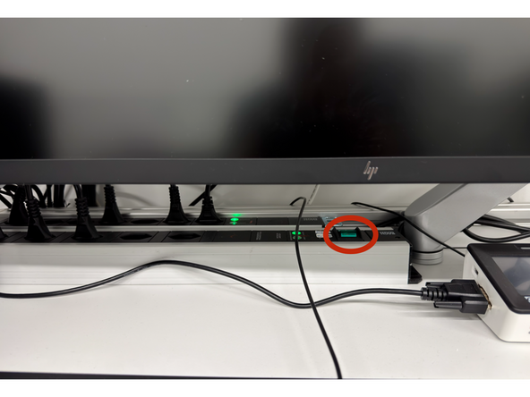
Switch on the front power strip.
-
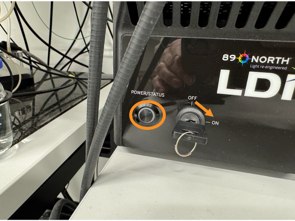
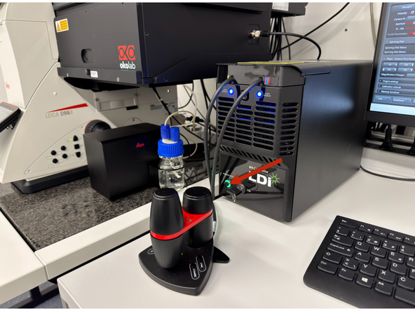
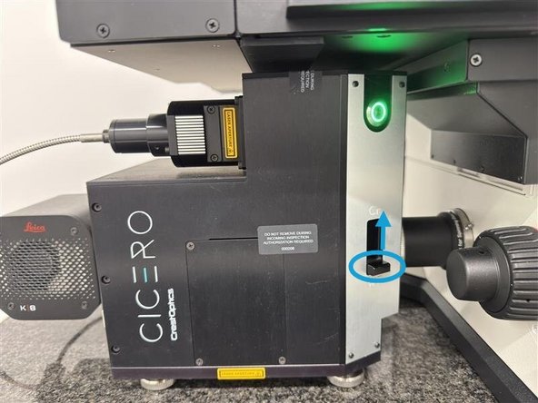
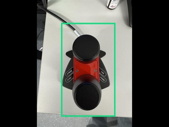
Press the Power/Status button briefly, then turn the laser key from OFF to ON.
-
Verify that the status LED ring turns green.
-
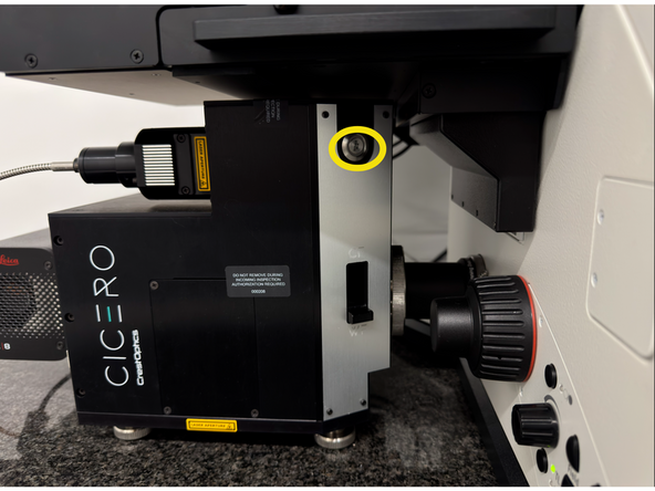
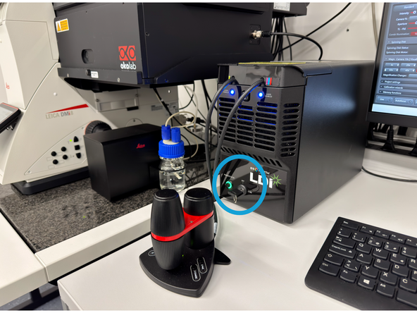
Press and hold the button on the spinning disk unit for ~2 seconds.
-
Wait until the LED status ring turns steady green.
-
-
-
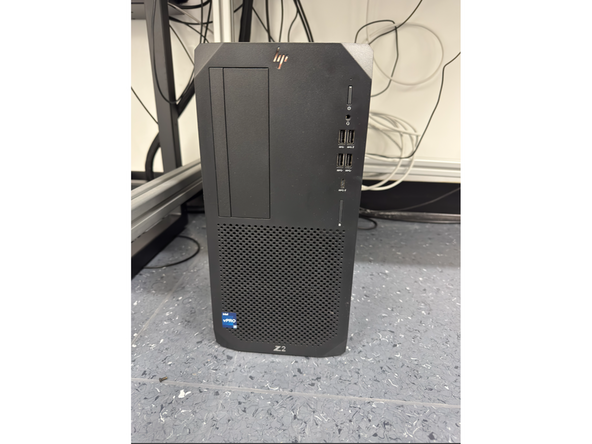
The PC must remain powered on at all times. Image data are initially stored locally on the PC and are transferred later to the server via the DataMover into the user's data folder. Do not shut down the PC.
-
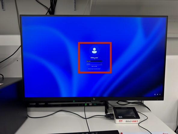
Log in using your Core credentials. If you have forgotten your password, follow this guide to reset it: Reset your Core account password
-
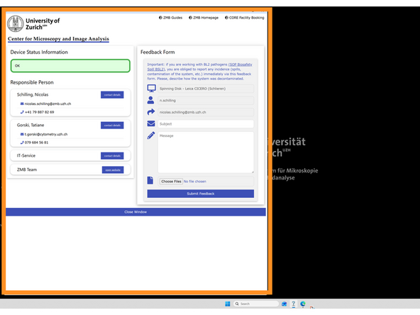
Wait for the feedback window that appears automatically after Windows login. This allows the PC sufficient time to establish connections with the hardware and helps prevent communication issues between the PC and the microscope.
-
-
-
Important: Before opening LAS X, ensure that the light engine LED status ring is green. If the LED ring is not green, the light source will not be controllable in the software later.
-
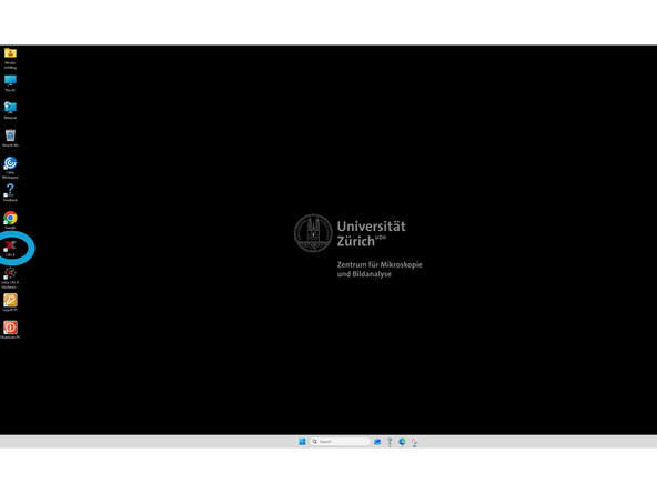
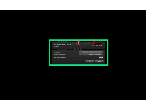
On the desktop, open LAS X.
-
In the pop-up window, keep the default settings: DefaultDynamicWidefieldTree.xlhw and Standard Configuration.
-
-
-
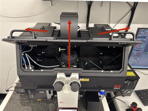
Slide the side panels at the top of the transmitted light arm to the side, then fold the transmitted light arm backwards and open the front flap of the Okolab incubator cage.
-
You can now load your sample onto the stage. The following sample holders are available:
-
Universal slide holder
-
4-slide holder
-
Mixed slide holder (1 slide + 2 × 35 mm dishes)
-
Universal well plate holder
-
-
-
Ensure the universal frame is properly spring-locked. As this is a multi-user system, always verify before imaging.
-
available sample carriers.
-
-
-
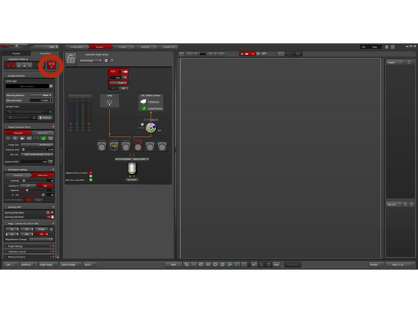
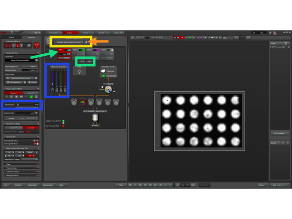
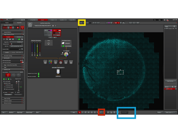
Click this icon to display the complete beam path. This view will then be loaded by default during your next imaging session.
-
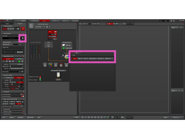
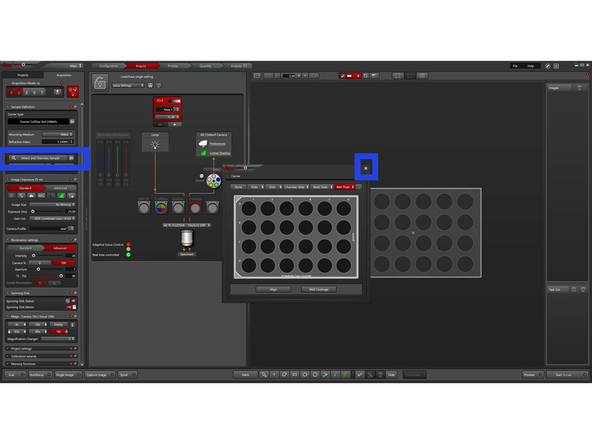
Click the Define Carrier icon and, in the pop-up window, define your sample type (e.g., slide, well plate, etc.).
-
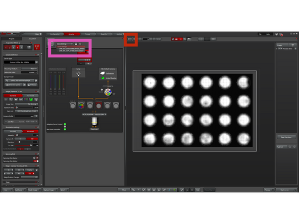
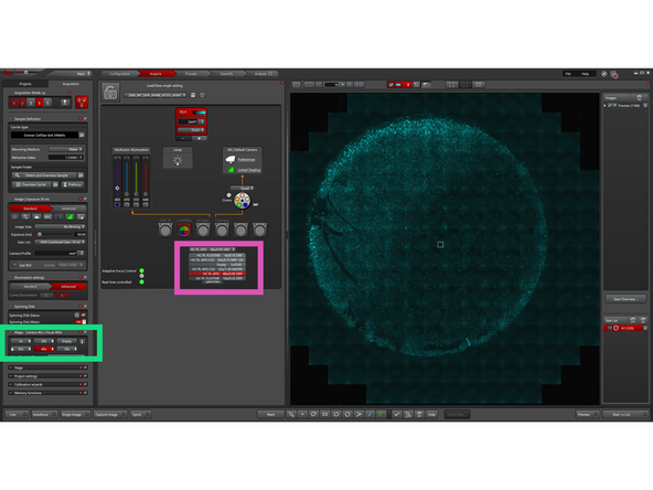
Close the pop-up window, then click Detect and Overview Sample.
-
The system now automatically performs the following steps: Using the 10× objective and AFC (Automatic Focus Control), it detects and aligns the bottom of the imaging carrier. The system then switches to the 4× objective and acquires a transmitted light overview image of your sample for later navigation.
-
-
-
Skip this step if automatic overview detection is used
-
Not all sample carriers are supported by automatic overview detection. If "Detect and Overview Sample" is greyed out, use the alternative method below with a spiral scan.
-
Move your sample above the 10× objective while visually observing the stage with the incubator cage open to guide positioning.
-
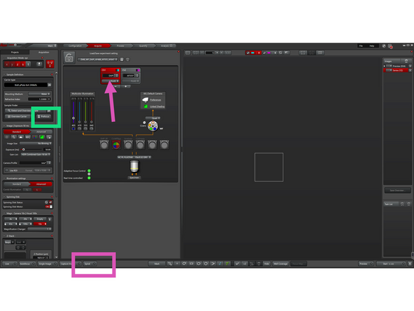
Click "Prefocus" to use hardware focus to approximate the focus position by detecting the coverslip reflection. Works best with the 10× objective and glass-bottom samples. Then fine tune focus with SmartMove joystick in "Live" mode.
-
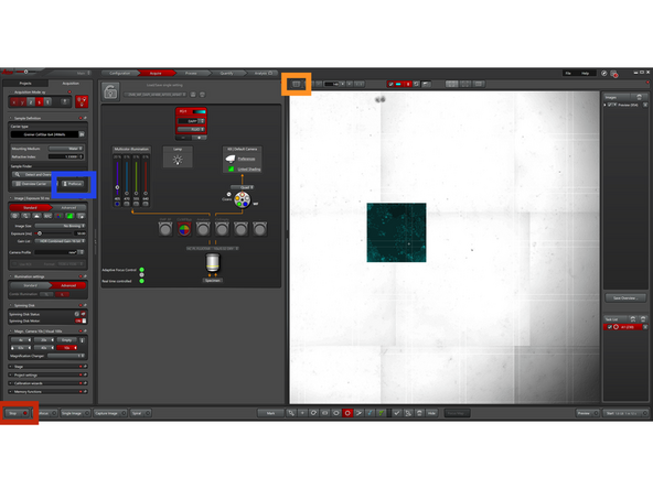
Click "Spiral" to start generating an overview image in a spiral scan using the active channel. We recommend using DAPI or transmitted light for most samples.
-
-
-
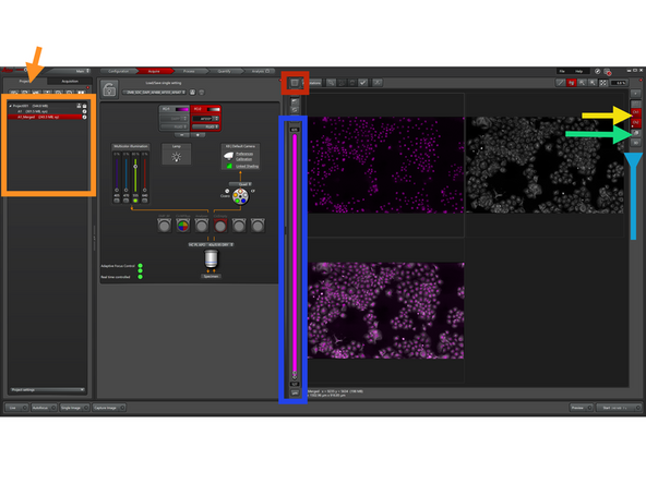
By default, you are in the Leica Navigator (see this icon).
-
The Leica Navigator allows you to navigate your sample, define multiposition experiments, or set up tiling experiments.
-
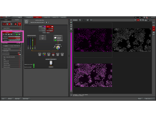
You can now load the default fluorescence settings from this dropdown menu:
-
WF for widefield
-
SDC for spinning disk confocal.
-
SDC always requires to physically insert Spinning disk ("CF") into beampath.
-
-
-
We recommend using the WF setting for initial focusing, as it collects emission signal from all planes, making it easier to find the correct focus.
-
The default settings use 20% illumination power and 50 ms exposure time. Depending on the sample, these parameters must be adjusted experimentally.
-
Remove any default channels you do not need using the “–” icon. "Red-Box" highlights active channel.
-
You can reload the default settings at any time or save your own settings for your personal use.
-
With LAS X 3.11, the light engine should switch automatically from red to green when Live is started after a laser interlock event. If this does not happen, check that the incubator cage is fully closed.
-
-
-
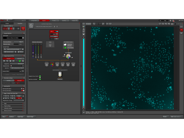
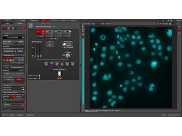
Click "Live"
-
Click the "Multichannel Viewer" icon to display the live view in a larger window.
-
Click "Prefocus" to use hardware focus to approximate the focus position by detecting the coverslip reflection. Works best with the 10× objective and glass-bottom samples.
-
Focus your sample using the Smart Move controller. Z-axis control XY stage movement You can switch between coarse and fine (precise) movement for all axes.
-
-
-
SDC always requires to physically insert Spinning disk ("CF") into beampath.
-
The default settings (SDC) use 80% illumination power and 150 ms exposure time. Depending on the sample, these parameters must be adjusted experimentally.
-
Compensation of light losses: In spinning disk confocal microscopy, only a small fraction of the excitation light passes through the pinholes (we loose up to 95% of light). To ensure sufficient signal for high-quality imaging, a high initial light intensity is required.
-
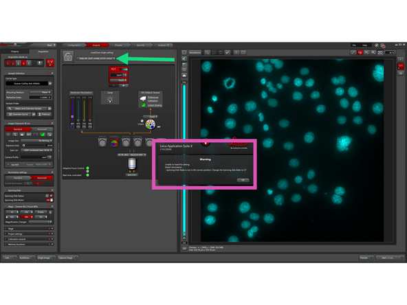
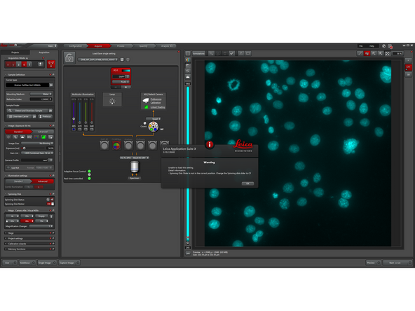
The warning pop-up appears only if SDC settings are loaded while the spinning disk slider is not in "CF" position. If this occurs, move the slider to "CF" and reload the SDC settings from the dropdown menu.
-
-
-
You can change objectives in 2 different ways:
-
While not in "Live" mode
-
While in "Live" mode
-
-
-
Optional Step: Skip this step when you are not using 63x 1.2 objective.
-
For long-term experiments (live-cell, multiposition etc.), the system uses Adaptive Immersion to automatically maintain the water droplet.
-
The system will automatically apply and maintain immersion water during imaging.
-
When switching objectives or moving to the loading position, the water droplet is removed automatically.
-
Note: The system is factory-installed and works automatically. No manual intervention is required during normal operation.
-
-
-
Optional Step: Skip this step when you are not using 63x 1.2 objective.
-
In conventional high-resolution microscopy, the correction collar must be adjusted manually to match the coverslip thickness or the refractive index of the sample.
-
SmartCORR automates this step by correcting spherical aberrations caused by optical mismatch. It reduces spherical aberrations and ensures optimal resolution and contrast, especially for deep imaging in 3D samples.
-
Click "Start SmartCORR" to automatically determine the optimal correction. The system acquires an image series and sets the optimal CORR position.
-
Requirements:
-
Sample must be in focus and fluorescent
-
Correct refractive index and embedding medium must be defined. In sample definition tab.
-
Available only in fluorescence (WF and SDC) mode with 63x 1.2 objective. Note: The objective is optimized for ~21 °C and 140–180 µm coverslips.
-
-
-
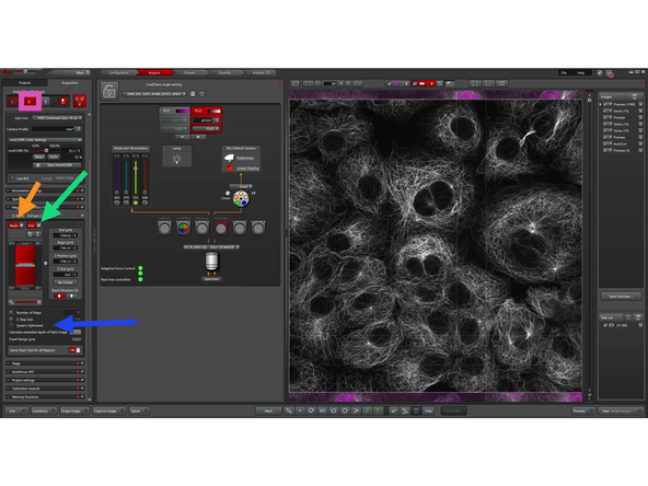
Enable "Z-Stacks".
-
Define your z-stack by setting the upper and lower boundaries of your sample.
-
Move to the desired start position and click "Begin"
-
Move to the end position and click "End"
-
Define the Z-step size or enable "System Optimized"
-
"System Optimized" automatically calculates the optimal Z-step size and number of steps based on the optical settings. This ensures proper sampling (Nyquist criterion) for accurate 3D reconstruction without unnecessary data.
-
The system will acquire images across the defined z-range.
-
-
-
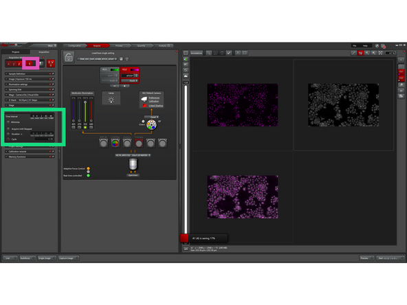
Enable "TimeLapse" to define how your sample is imaged over time.
-
Set the Time Interval between acquisitions
-
Enable "Minimize" for maximum acquisition speed (optional)
-
Set the number of cycles or total duration
-
(Optional) Enable "Acquire Until Stopped" for continuous imaging
-
The system will acquire images at the defined time intervals.
-
-
-
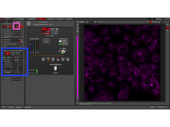
Leica systems typically offer three focus strategies to keep images sharp either by mapping the sample surface, computing focus from image contrast, or actively locking focus with dedicated hardware.
-
Click on Autofocus Panel to be able to see the different strategies:
-
Software Focus: Image-based autofocus using a contrast/sharpness metric. Runs a short Z-search and selects best focus. Flexible but slower; good for occasional refocus when no reliable reflective plane exists.
-
AFC (hardware focus): Optical focus lock using reflection (typically at coverslip–medium interface) to track and correct Z-drift in real time. Very fast and stable for long time-lapse/live imaging.
-
In order to generate a "Focus Map" make sure you are in "Navigator" interface.
-
Focus Map: Define focus at several XY points to model sample tilt/curvature. The system interpolates Z between points during acquisition to maintain focus across tiles/wells, ideal for uneven samples and large area scans.
-
Distribute focus map points across your tile region. Use at least four points, depending on sample complexity.
-
Select the first focal point in the image or table, then define its focal plane manually with "Set Z" or automatically with "Set by Autofocus". Use "Find all by Autofocus" to detect all remaining focal planes automatically.
-
-
-
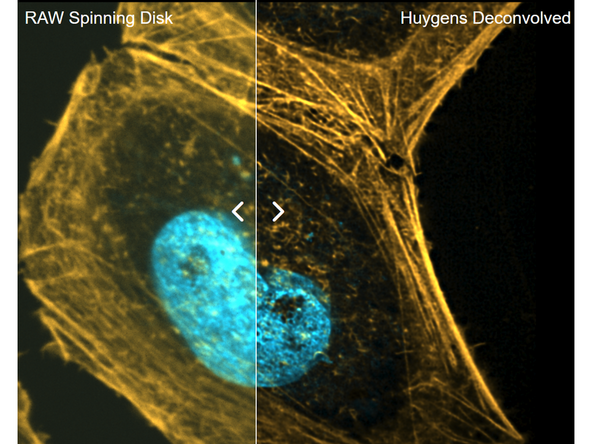
While spinning disk confocal imaging already provides good optical sectioning, additional deconvolution can further reduce residual out-of-focus blur and improve contrast and resolution. See also: Image Deconvolution using SVI Huygens
-
-
-
Binning combines neighboring camera pixels into one larger pixel. For example, with 2 × 2 binning, four pixels are merged into one.
-
This increases signal per pixel and reduces the data volume, allowing faster acquisition, but at the cost of spatial resolution.
-
You could use binning when signal is low or speed is critical:
-
Live-cell imaging to reduce exposure time and phototoxicity
-
Fast dynamics where high frame rates are required
-
Low signal samples to improve signal-to-noise
-
Overview scans where maximum resolution is not needed
-
-
-
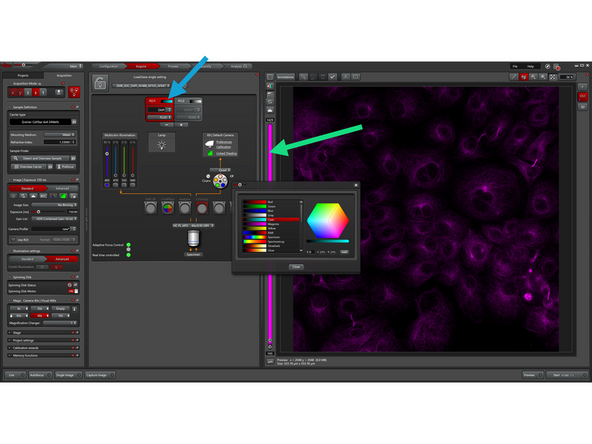
In general, the selection of a suitable look-up table for a specific use depends on the user's own judgment and needs.
-
You can assign a specific LUT to a channel by double-clicking here.
-
You can temporarily assign a specific LUT to an acquired channel by double-clicking on the histogram bar.
-
-
-
To review acquired images, ensure you are in the "Multichannel Viewer" interface.
-
Open the "Project" tab and select the dataset you want to view in the Image tab.
-
Select which channels to display.
-
Click "MIP" to generate a temporary maximum intensity projection.
-
Click "3D Viewer" to visualize your data in 3D.
-
Adjust the histogram and modify the LUT to optimize image display.
-
-
-
By using auto-save, there is less risk of data loss during an extended image acquisition session and long file saving times after an extended imaging session can be avoided. Since auto-save does not generate standard Leica .lif files, we also show how the resulting files can be handled and visualized.
-
-
-
-
Save data to the E:\automatic_transfer\files\n.schilling: drive. The network can be slow and unstable, especially for large 3D datasets and live-cell experiments.
-
In the automatic transfer folder, create a subfolder named with your Core username (e.g., n.schilling).
-
After exporting, close the software and log off.
-
Leave all other hardware powered on. Do not shut down any additional components.
-
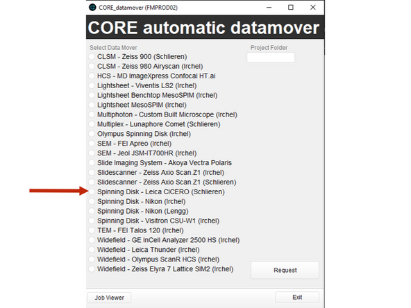
Use Citrix to initiate data transfer via the ZMB DataMover from the local CICERO PC to the server infrastructure.
-
Access Citrix via the app or through the browser: vdi.core.uzh.ch
-
Select in Datamover Leica CICERO SDC
-