-
-
You can take an image of the shuttle inside the chamber with the Nav-Cam. This can help you to recognize your samples on the CCD, SEM of FIB images, but it is not necessary for the AutoGrid shuttle.
-
In the xTUI window select Stage > Take Nac-Cam Photo.
-
The microscope will automatically move to the Nav-Cam position, acquire the image and move back to the initial position.
-
-
-
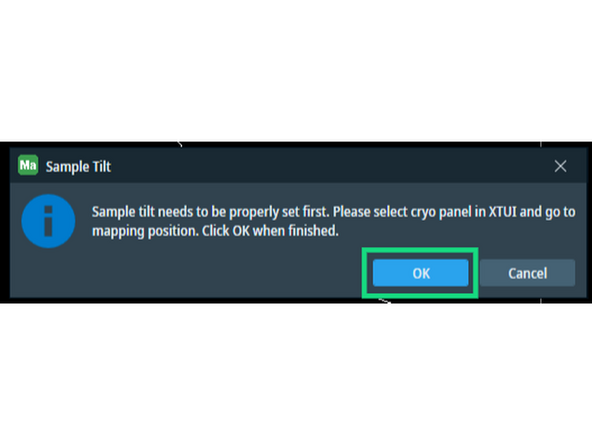
Go to Mapping Position on Grid 1 or 2. This will move the respective grid perpendicular and centered to the electron beam.
-
Zoom in and focus on the surface of the grid either with the auto-functions...
-
... or manually by right-clicking on the SEM image and dragging the mouse vertically.
-
Link the current Z height to the working distance.
-
Cross-check if the stage Z position is ca. 4 mm.
-
-
-
The icons of all necessary software can be found on the right side of the right-most display.
-
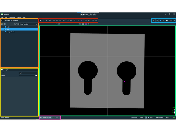
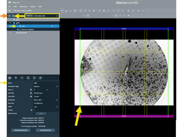
Open Maps and familiarize yourself with the overview:
-
Layer management
-
Details and modification of currently selected layer element
-
Image window
-
Image acquisition buttons
-
Job Control and Run scheduled jobs
-
Actions on the image window (measurement, place tileset, export snapshot)
-
-
-
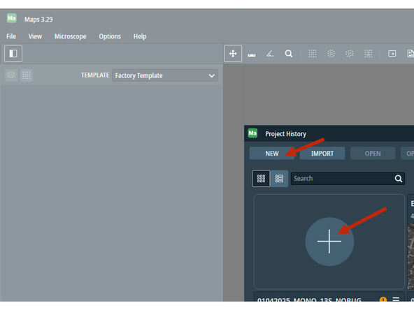
Upon opening of Maps, create a new project for your session.
-
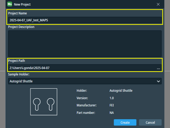
Give a meaningful name to your project and set the right folder path.
-
Project name: Date_ProjectID_SampleID_Maps and Project Path: Z:\Users\i.gonda\Date
-
Please save your data in the mounted folder Z:\Users\u.sername . This disc is physically the Support PC D:\ drive and your data can be easily transfered from here.
-
Make sure your shuttle is in mapping position, perpendicular to the electron beam.
-
-
-
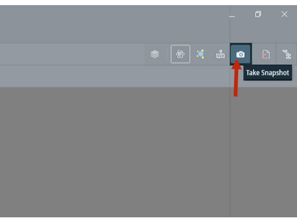
Take a SEM snapshot of your grid, that will guide the placement of the Atlas tile-set.
-
Add new layer for each grid.
-
Select "mammalian cells" template from the drop-down list and add tile-set on your grid. Then adjust tile-set position on the previously taken SEM snaphot.
-
Repeat these tasks for Grid 2 as well: change mapping position to grid 2, acquire SEM snapshot and add Atlas tile-set.
-
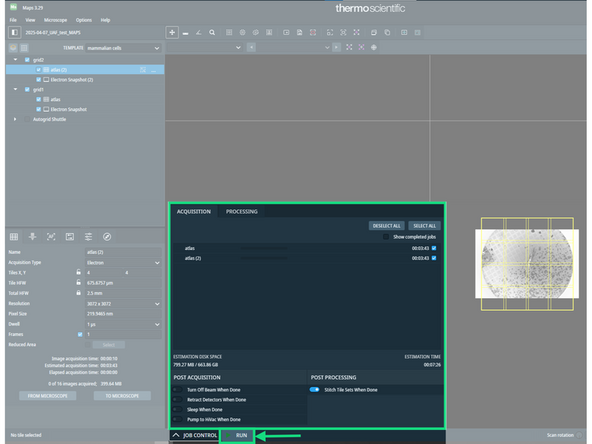
Check in Job Control the scheduled tasks and hit Run.
-
-
-
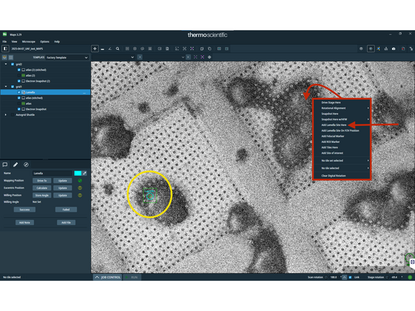
Right-click at positions, where you would like to mill lamellae.
-
Select Add Lamella Site Here.
-
Added lamella positions will show up with a turquoise marker.
-
-
-
The GIS needle will not insert if the Z-height and Working Distance are not linked. If you missed this step, please visit Step 2.
-
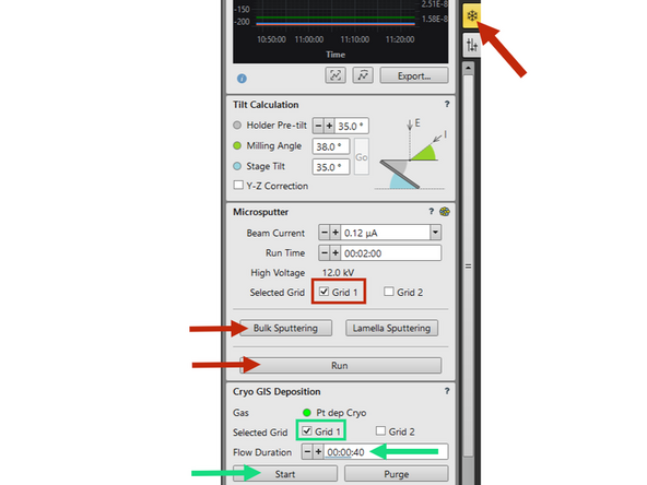
First you need to create a thin layer of platinum over the sample by microsputtering. In the Cryo tab, select the grid(s) you wish to coat, choose Bulk Sputtering parameters and hit Run.
-
After the Pt layer, you need to deposit a organometallic layer, that will protect the front of your lamella. This gasous compound in precipitated on the cold surface from the Gas Injection System (GIS). Optimal times vary between devices and the sample; on this device it is typically 20-40 seconds.
-
Select the grid(s) you wish to coat, choose an appropriate flow duration and hit Start.
-
Finally, coat your grid again with a thin layer of Pt using the microsputter tab (red instructions). This will reduce surface charging.
-
-
-
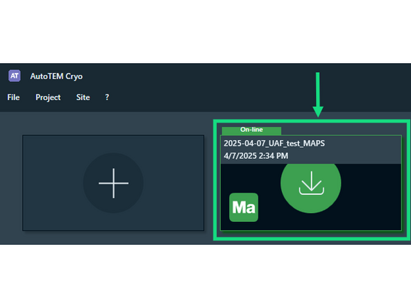
Open AutoTEM. You find the shortcut on the right side of the right-most display.
-
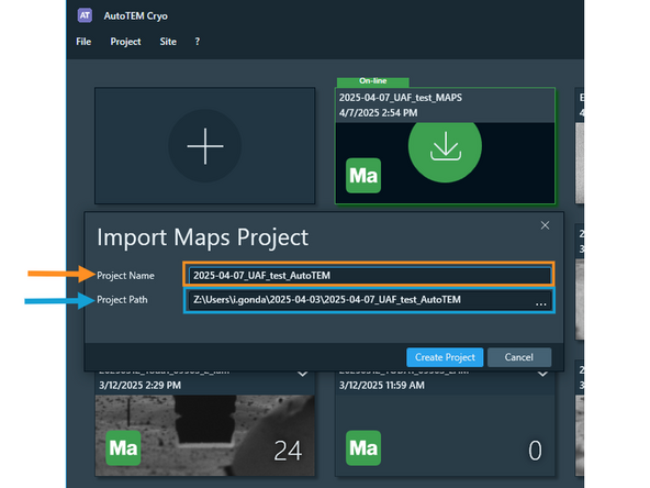
AutoTEM recognizes the currently on-line (open) Maps project and offers to import it and create a AutoTEM project from that.
-
A good convention is to change the "_Maps" ending of the project to "_AutoTEM".
-
Make sure the AutoTem project is also saved in the same folder as your Maps project.
-
-
-
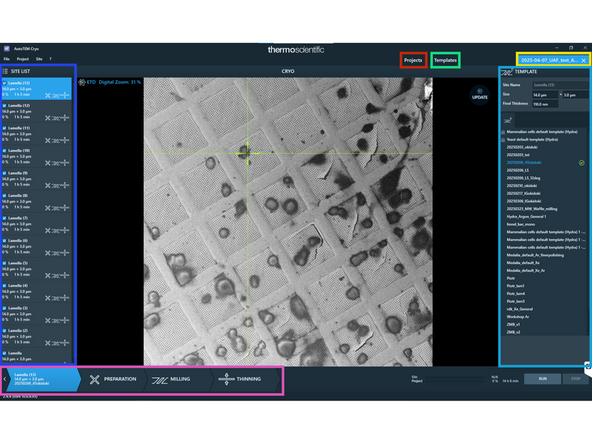
Top bar: Project overview
-
Top bar: Template editor
-
Top bar: Access currently open project
-
Bottom bar: Lamella preparation workflow
-
Left sidebar: List of lamella sites (project view) or List of templates (template editor)
-
Right sidebar: Available templates or Template editor
-
-
-
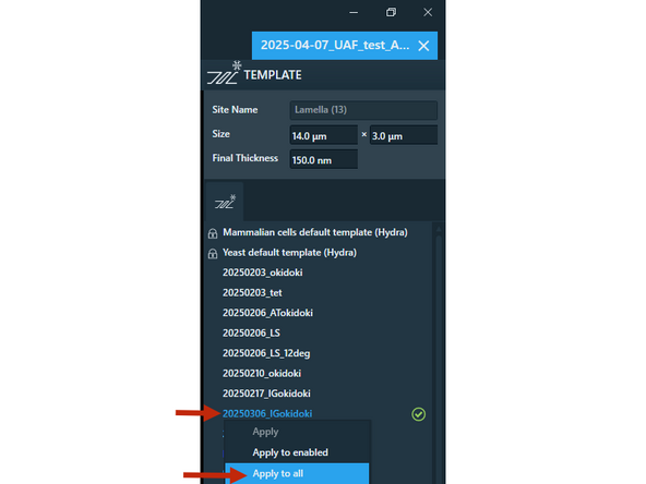
Apply your carefully adjusted template for the lamella sites. Right click on your template (right-side panel) and select Apply to all.
-
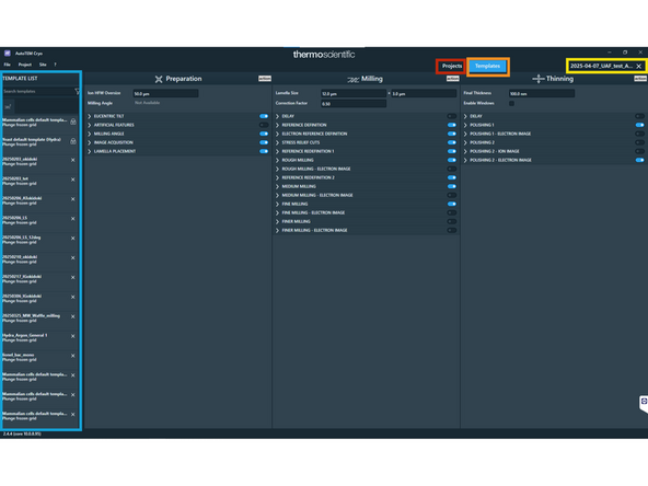
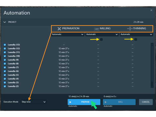
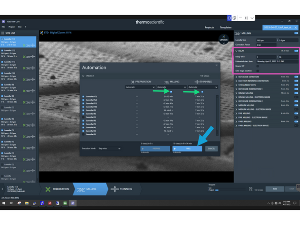
Lamella preparation times are listed in 3 columns for the three steps: Preparation, Milling and Thinning. When setting up lamella make sure to execute Step-wise (NO Site-wise).
-
For lamella site preparation, untick the Milling and Thinning steps. You will need to manually adjust and confirm the position of each lamella.
-
Start site preparation with the Prepare button. It takes ca. 6-8 mins per lamella.
-
-
-
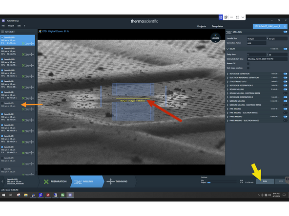
Adjust lamella position and nominal lamella thickness. A nominal 110nm thickness corresponds to ca. 180nm thick lamellas)
-
You may untick lamella sites, that you don't want to mill (due to time restrictions or bad grid square).
-
Click Run to start milling.
-
Tick on Milling and Thinning steps.
-
Adjust delay on the first lamella on the top of the list. Ideally, you want to unload just after the milling has finished.
-
Untick Beams Off and Safe stage position. Otherwise, the milling starts immediately. (This is a software bug, guide will be updated, if bug is fixed.)
-
Hit Mill to start milling.
-