
Introduction
In this guide of the Center for Microscopy and Image Analysis we describe the major steps/aspects required for generating tiled overviews or setting up several positions for automated acquisition. Additionally, the guide will provide explanations of various focus strategies that are useful for obtaining overviews and conducting long-term experiments.
For start-up of the system, mounting and focusing a sample, setting up imaging parameters as well as finishing your session please check corresponding guides.
This guide is valid for both modalities, LSM mode as well as Airyscan mode.
Please find more information about the system here.
-
-
"Navigation & Tiles" is used to pre-define areas of interest or positions of interest which can then be acquired automatically .
-
Different tools are available in the stage view to draw tile regions you would like to acquire.
-
Please see the following steps/short videos for detailed descriptions of each available tool.
-
The tile regions ("TR") are created for each marked region. They are added to the list in the "Tile Regions" within "Tiles" tab.
-
The tile positions are created for each marked position. They are added to the list under "Positions" within the "Tiles" tab.
-
-
-
Within "Navigation & Tiles" container select "Setup by predefined" tool.
-
The "predefined toolbar" is displayed as the top tool bar.
-
In the top toolbar select the desired contour tool (rectangle or circle).
-
Choose the desired dimensions, like how many tiles in x,y dimension (rectangle) or diameter (circle).
-
Within the stage view select region where the tiles regions should be added.
-
Click "Add Tile Region" on the top toolbar.
-
You can also add a predefined tile region at the current stage position by pressing the F9 button on your keyboard. The size of the region is the last defined number of tiles in x and y, or a square of 3x3 tiles if you have never defined a region before.
-
The tile regions ("TR") are created for each marked region. They are added to the list in the "Tile Regions" within "Tiles" tab.
-
-
-
Within "Navigation & Tiles" container select "Setup by contour" tool.
-
The "contour toolbar" is displayed as the top tool bar.
-
In the top toolbar select the desired contour tool (rectangle, circle or free hand).
-
Within the stage view draw/mark your region(s) of interest being acquired later.
-
The tile regions ("TR") are created for each marked region. They are added to the list in the "Tile Regions" within "Tiles" tab.
-
-
-
Within "Navigation & Tiles" container select "Setup by stake" tool.
-
The "stake toolbar" is displayed as the top tool bar.
-
Define a tile region by the placement of at least two markers. If you want to modify the tile region (expand/reduce) you have to adjust the tile region to the desired size.
-
In the top toolbar select the desired contour tool (rectangle, circle or free hand).
-
To complete the tile region press "Done".
-
The tile regions ("TR") are created for each marked region. They are added to the list in the "Tile Regions" within "Tiles" tab.
-
-
-
Within "Navigation & Tiles" container select "Setup by carrier" tool.
-
The "Tiles carrier toolbar" is displayed as the top tool bar.
-
Make sure you have selected and calibrated a sample carrier by AI Sample finder.
-
In the "Carrier" tab, select the individual wells for which you want to create the tile regions by pressing the "CTRL" key and clicking on the desired wells. The selected wells are now bordered by a blue circle.
-
In the top toolbar, select "Fill Factor" and enter the desired value (%) in the input field.
-
Click "+".
-
According to the selected "Fill Factor" the wells will be filled with a calculated number of tiles that are located around the center. To create a given size of tile region use the "Columns/Rows" function in a similar manner.
-
The tile regions ("C") are created for each marked region. They are added to the list in the "Tile Regions" within "Tiles" tab.
-
-
-
Within "Navigation & Tiles" container select "Setup by location" tool under "Positions".
-
The "Positions Location Toolbar" is displayed as the top toolbar.
-
Add positions as follow:
-
In the top toolbar click "+" followed by clicking on the location where you want to add a position with the stage view.
-
In the top toolbar click "arrow", in the stage view move to a desired area and then click "Add Position" on the top toolbar.
-
The added positions are displayed in the stage view and within the "Single positions" list under "Positions" of the "Tiles" tab.
-
You can also add a single position at the current stage posistion by pressing the F10 button on your keyboard.
-
-
-
Within "Navigation & Tiles" container select "Setup by array" tool under "Positions".
-
The position array toolbar is displayed as the top toolbar.
-
In the top toolbar select the desired contour tool (rectangle or circle).
-
Adjust "Number" of required positions and the "Bias" to define distribution of the positions.
-
Mark the area of interest in the stage view area (left mouse button).
-
The positions will be generated automatically.
-
The added positions are displayed in the stage view and within the "Position Arrays" list under "Positions" of the "Tiles" tab.
-
-
-
You have selected and calibrated a sample carrier by using AI sample finder.
-
Within "Navigation & Tiles" container select "Setup by carrier" tool under "Positions".
-
The positions carrier toolbar is displayed as the top toolbar.
-
In the "Carrier" tab, select the individual wells/containers in which you want to add/distribute positions by pressing the "CTRL" key and clicking on the desired wells. The selected wells are now bordered by a blue circle.
-
Adjust "Number" of required positions and the "Bias" to define distribution of the positions. Alternatively, if you want the positions as grid, adjust the columns, rows and overlap.
-
Click "+" to add the positions to the selected containers/wells.
-
The added positions are displayed in the stage view and within the "Position Arrays" list under "Positions" of the "Tiles" tab.
-
-
-
Add a Tile region via various options described previosuly.
-
Activate the Tile region where you want to add support points in order to generate a focus map.
-
Under single support point, click on current position to add manually support points.
-
While you add manually supports point, make sure you are live and have also adjusted you Z-value as this will be automatically included when you click on "current position".
-
Make sure focus strategy is set to"use z values by tile setup".
-
-
-
Add a Tile region via various options described previosuly.
-
Activate the Tile region where you want to add support points in order to generate a focus map.
-
Under the "add multiple support points" section either choose from drop down menu "generic" or "onion skin".
-
Define your "Rows" and "Columns".
-
Click on "distribuite".
-
Click on "verify"
-
Manually adjust in live view focus and click "next" when focus is defined. Alternatively you could also asign "Software autofocus" but will be slower than manual.
-
Make sure focus strategy is set to "use z values by tile setup".
-
-
-
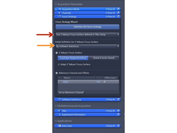
Choose "use z values/ defined by tile setup".
-
Additional or update focus actions can be activated to adapt the z vales.
-
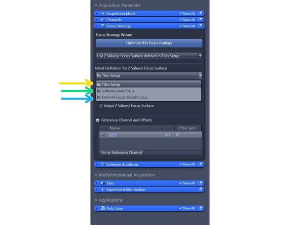
The fixed z-values from the tile setp are used as the inital values.
-
The initial z-values are determined by a speartate sotware autofocus autofocus run on each support point/position/ tile region.
-
The initial z-values are determined by recalling the prevuiously stored focus (distance to coverglas) with the definite focus on each support point/position/tile region. This is typically the surface with an additional offset.
-
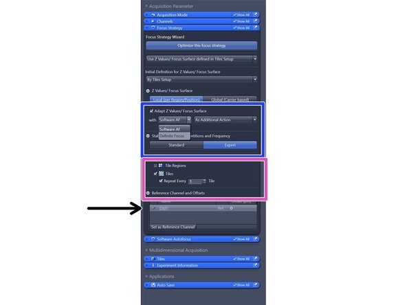
The focus surface and z values are used as the starting point for an additional focus action which updates the z-values.
-
This loops iterates over the individual tiles of one regions in a tiles experiments.
-
Set reference channel and offset.
-
-
-
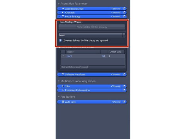
If you choose focus strategy "None", Z-values defined by tile setup will be ignored.
-
The current z-position at the time the experiment is started is set as the reference Z-position and remains unchanged during the experiment.
-
-
-
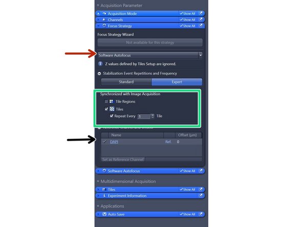
If you choose "Software autofocus" as focus strategy then the Z-values defined in tile setup will be ignored and Z-value will be defined by "Software autofocus" exclusevly.
-
This loops iterates over the individual tiles of one regions in a tiles experiments.
-
Set reference channel and offset for software autofocus.
-
-
-
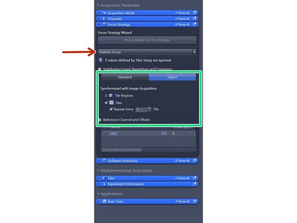
Definite focus tries to maintain a certain distance to the cover glass of the sample in order to compensate for mechanical and thermal movements.
-
The definite focus is initialized at the start of the experiment by setting the current distance as the reference distance.
-
This loops iterates over the individual tiles of one regions in a tiles experiments.
-
-
-
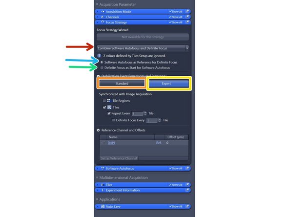
This strategy allows you to combine the functions of definite focus and software autofocus.
-
Standard: Use the standard setting for the stabilization events. The stabilization is executed on each time point and each tile /position.
-
Expert: All settings for the stabilization events are shown and can be modified.
-
Software autofocus moves the focus drive to the focus position that has been calculated. Taking this as the starting point, a new reference distance is defined for the next distance stabilization performed by Definite focus.
-
This can reduce the likely-hood of a stabilization failure when the sample is long and elongated and the carrier possibly tilted.
-
The last valid reference Z-position defined by definitite focus is the starting position for the software autofocus search. This allows you to optimize the search range and step size of the software autofocus.
-
-
-
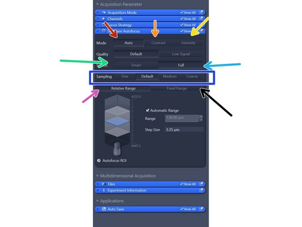
The autofocus will maximize either contrast or intensity depending on the hardware configuration.
-
The autofocus will maximize local contrast.
-
The autofocus will maximize he total intensity.
-
use if the sample covers most of the field of view.
-
Use if sample contains few structuures (e.g. beads or noisy images) and for calibration sldies.
-
step size (Fine: 0.5x, Default: 1x, Medium: 2x, Coarse: 4 x depth of focus)
-
Searches alwas around the positon at whioch autofocus is started.
-
Search in the range shown in the range control.
-


Cancel: I did not complete this guide.
One other person completed this guide.