Introduction
In this guide of the Center for Microscopy and Image Analysis you will learn how to acquire images on the the Olympus Spinning Disk using the scanR acquisition software.
The scanR software is intended for automated screening-type image acquisition. Here we will introduce you to the software interface and explain how to set up your screen.
Please find detailed information about the microscope here.
-
-
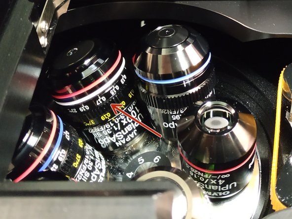
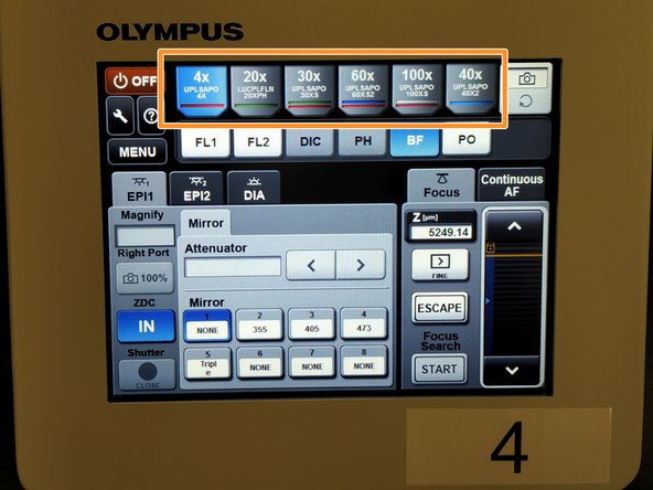
Make sure the 4x objective is selected and in the lowest z-position:
-
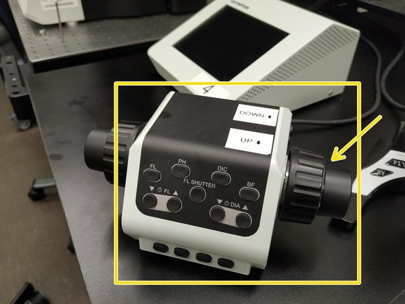
On the microscope touch panel (Sticker #4) press "Start Operation".
-
Choose the "4x" objective.
-
Move the objective to the lowest z-position by pressing the downwards arrow.
-
-
-
Double-click on the "scanR Acquisition" Icon.
-
-
-
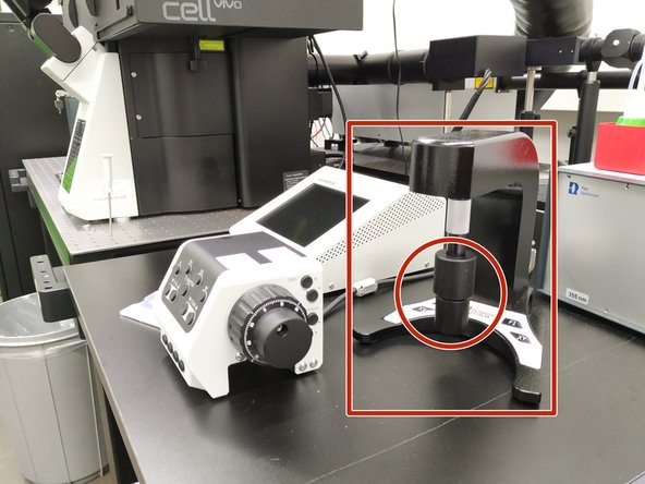
Depending on the used objective, the correction collar should be set to the correct cover glass thickness and incubation temperature.
-
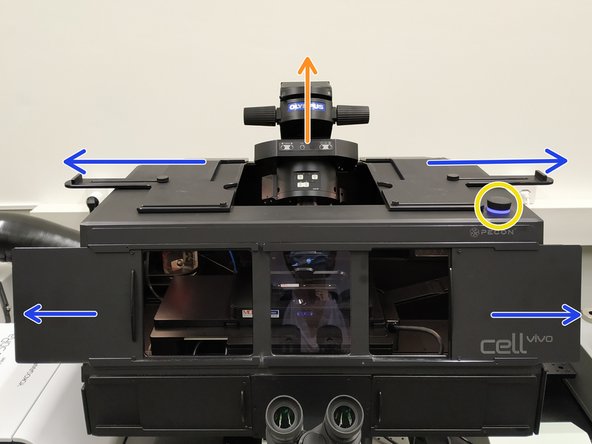
Open the doors and top-sliders of the incubation box to get access to the stage.
-
Turn ON the incubation box light.
-
Gently, push back the condenser arm.
-
Check that the correction collar of your objective is set correctly.
-
-
-
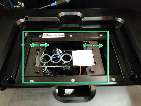
Different sample carriers can be used:
-
Glass Slides, chamber slides or petri-dishes by using the universal adjustable stage insert.
-
Removing the universal stage insert allows for inserting well plates.
-
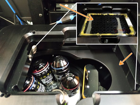
Place your sample with the cover slip facing down.
-
Navigate your sample in x and y using the external controller.
-
Pull back the condenser arm.
-
-
-
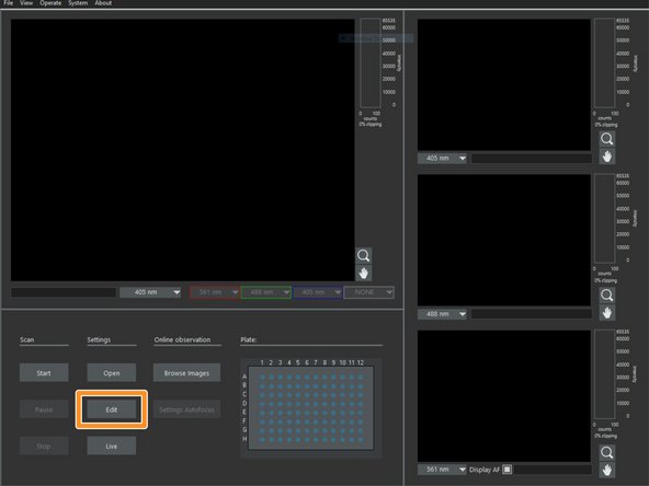
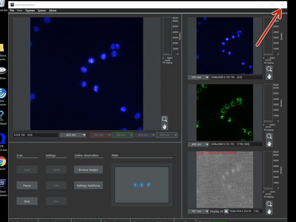
Settings of the previous scan will be automatically loaded upon software start.
-
Click "Edit" for modifying and/or verifying scan settings. A new window opens ("Edit Scan" Window).
-
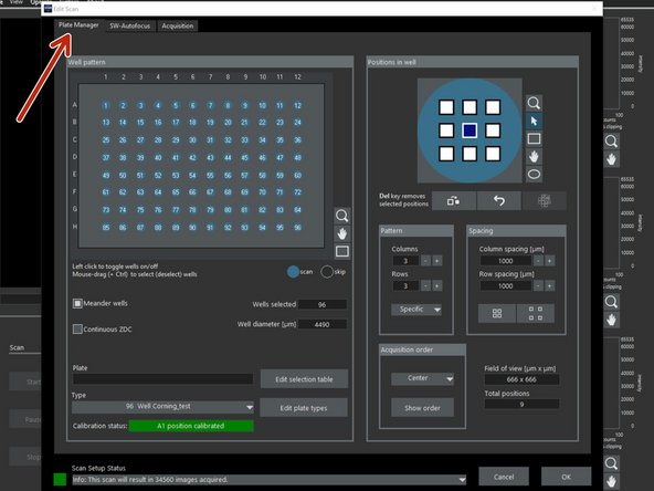
Open the "Plate Manager" tab.
-
-
-
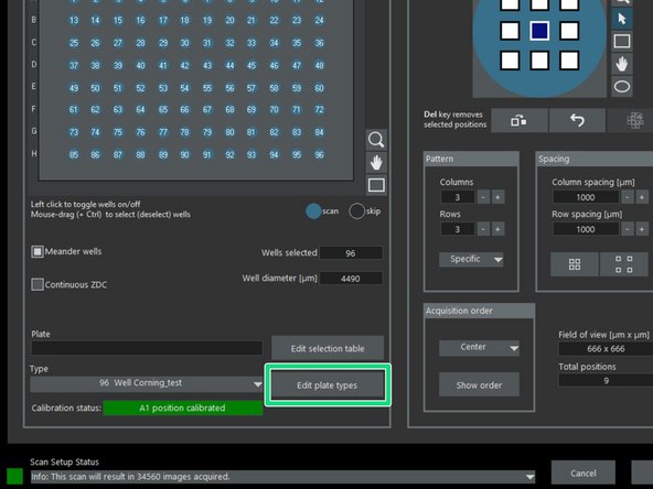
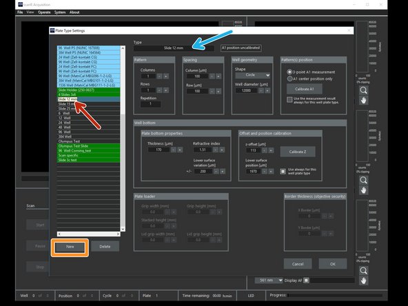
Select "Edit plate types".
-
Use an existing template and adapt it according to your needs.
-
Choose an existing template from the list that you would like to adapt, e.g. "Slide 12 mm".
-
Press "New" to create your own profile.
-
Rename your template.
-
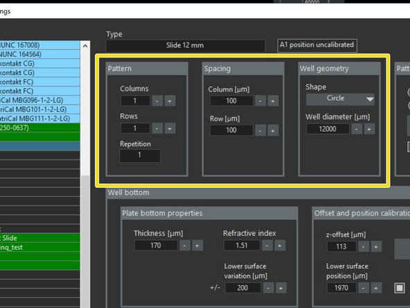
Define the "Pattern", "Spacing" and "Geometry" of your wells/cover slips.
-
-
-
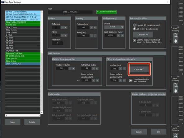
Press "Calibrate Z" to go to "Live View".
-
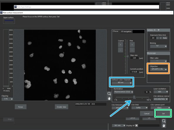
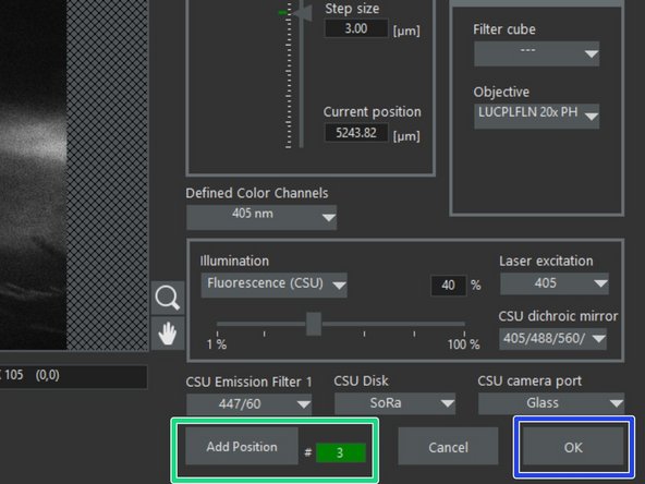
Define the "Defined Color Channels" (e.g. 405 nm) and adapt laser intensity accordingly.
-
Select the desired objective.
-
Focus your sample using the microscope focus wheels.
-
Press 'Set" once you are done.
-
-
-
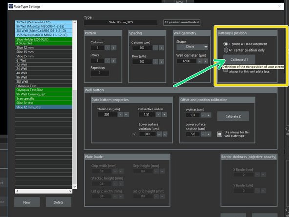
Calibrate your "Pattern(s) postion" using either:
-
"3-point A1 measurement". Triangulation method.
-
"A1 center position". Only center of of the well/cover slip defined.
-
Press "Calibrate A1".
-
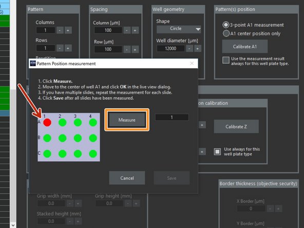
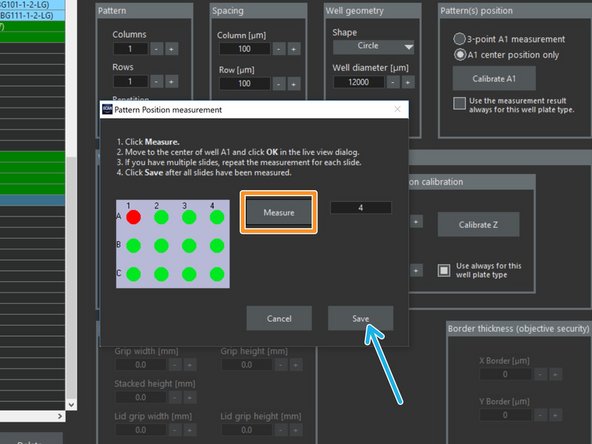
On the "Pattern Position measurement" window select which slide/well you want to measure.
-
Click "Measure" for "Live View".
-
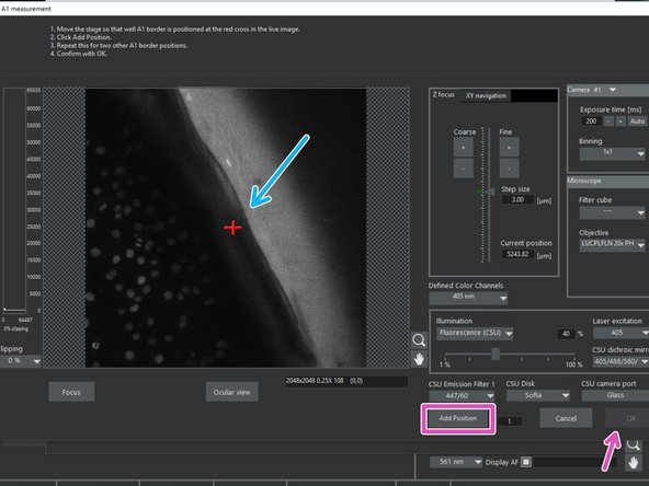
Move the stage that the red cross is at the border of the slide (if "3-point A1 measurement" was selected), or make sure the objective is located underneath the center of the well/cover glass ("A1 center position" selected).
-
Click "Add Position" (for "3-point A1 measurement") or click "OK" (for "A1 center position" strategy).
-
-
-
Repeat this for the two other reference points of A1 (if "3-point A1 measurement" was chosen).
-
The "#number" will turn green as soon as 3 points have been measured.
-
Confirm with "OK".
-
If applicable, repeat and click "Measure" in order to define several cover slips on the slide.
-
If well plates are used it is sufficient to measure only one well, as the spacing and pattern is already defined by the template.
-
After all positions have been measured confirm by clicking "Save".
-
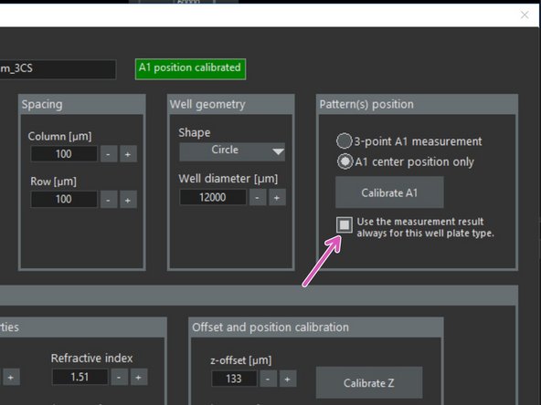
Check in order to apply this measurement everytime this plate definition is used. Represented by the green statement "A1 position calibrated".
-
-
-
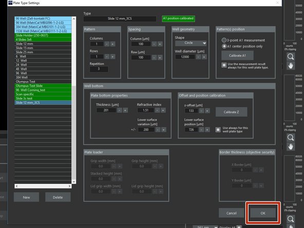
Once you are satisfied with your plate settings confirm with "OK".
-
-
-
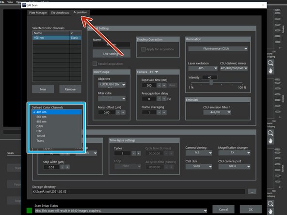
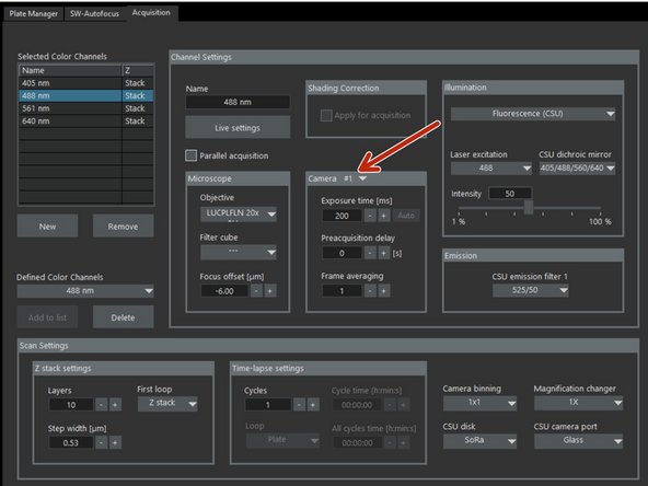
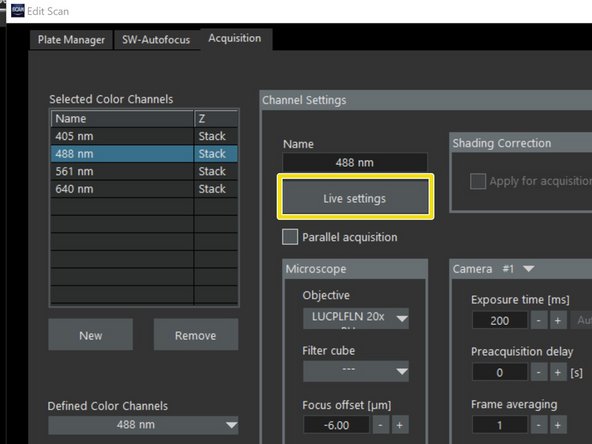
In the "Edit Scan" window go to the "Acquisition" tab.
-
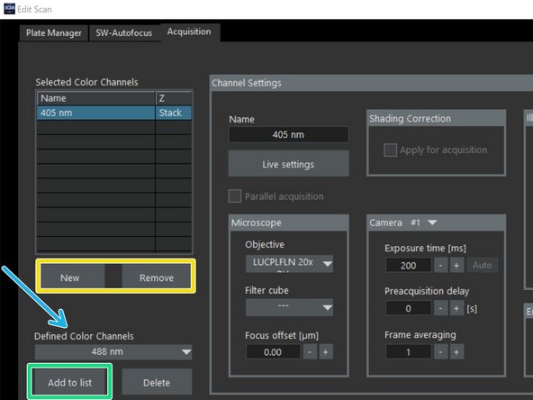
Select the desired channels for acquisition in the list "Defined Color Channels".
-
Click "Add to list".
-
You can also create new channels or remove them from the list.
-
-
-
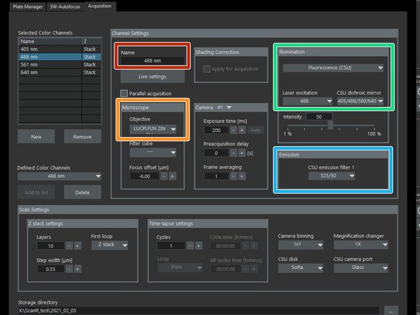
When using an existing or defining a new channel please confirm/adjust:
-
Naming.
-
Desired "Objective".
-
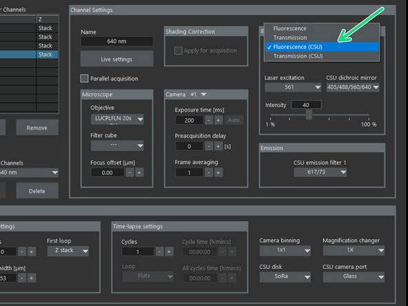
"Illumination" type (choose "Fluorescence (CSU)"), "Laser excitation" (e.g. 561), and the correct "CSU dichroic mirror".
-
Be aware that currently ONLY the "CSU illumination" types are working. Please do not select any other.
-
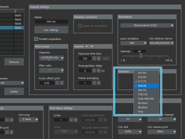
Correct "CSU emission filter 1/2".
-
For information on the filters, mirrors etc please refer to the instrument webpage.
-
-
-
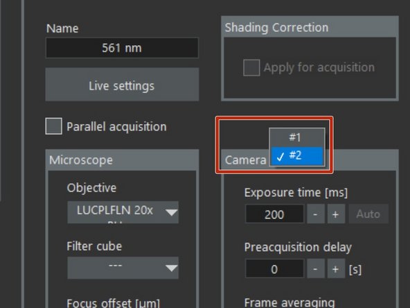
Define which camera to be used for each channel.
-
If dual camera acquisition is used for simultaneous acquisition of two channels with maximum speed:
-
Choose Camera #1 for one channel and Camera #2 for the other channel which should be linked.
-
For Camera # 2 only 405nm and 488nm excitation can be chosen due to the available emission filters.
-
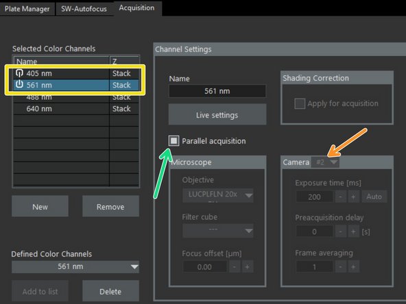
Important: Be sure that the two channels which should be linked are in the correct acquisition order. Channels can be dragged up and down for changing order.
-
Activate "Parallel acquisition". A linker is displayed between the two channels.
-
-
-
Press "Live settings" to check settings of the chosen channel in live view ("Live settings control").
-
This should only be done after z has been calibrated (see step 7).
-
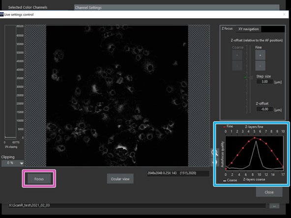
The system will first perform a complete hardware and software auto-focus run.
-
Press "Focus". The AF settings will be applied.
-
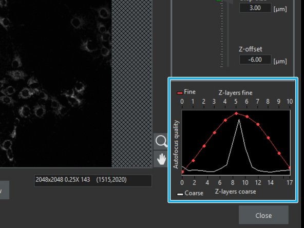
The AF settings can be optimized with the help of the autofocus quality graph.
-
-
-
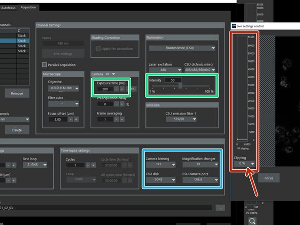
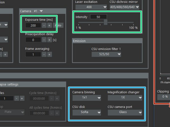
Move the "Live settings control" window to the side for full view of the "Channel settings".
-
Adjust Laser "Intensity" and "Exposure time" for each channel.
-
Avoid saturation - "Clipping" should be 0%.
-
Set here which "CSU disk" (50 um or SoRa disk) should be used for acquisition, as well which "Magnification changer", and if "Camera Binning" should be applied.
-
-
-
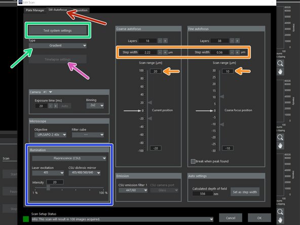
Go the to the "SW-Autofocus" tab .
-
Define the "Illumination" Channel for the autofocus.
-
Make sure the "Type" "Gradient" has been chosen and Click "Test system settings".
-
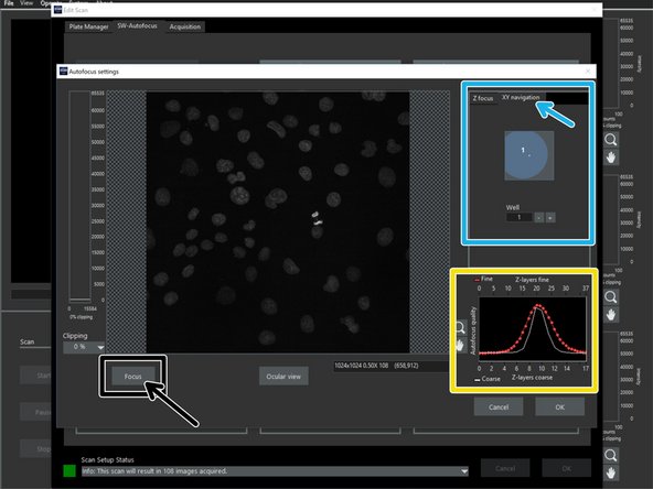
In the "Autofocus settings" click "Focus".
-
If the focus is not ideal adjust the step size and/or range accordingly.
-
The SW-Autofocus settings can be optimized with the help of the autofocus quality graph.
-
One can also navigate to different sample coordinates via "XY navigation" for further testing.
-
For time-lapse acquisitions one can chose in which acquisition cycles the autofocus should be applied.
-
-
-
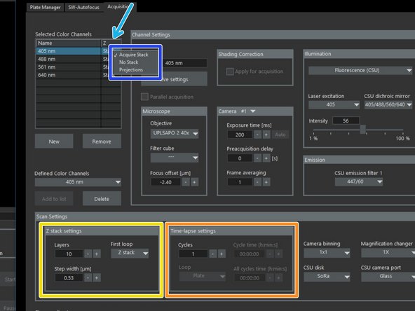
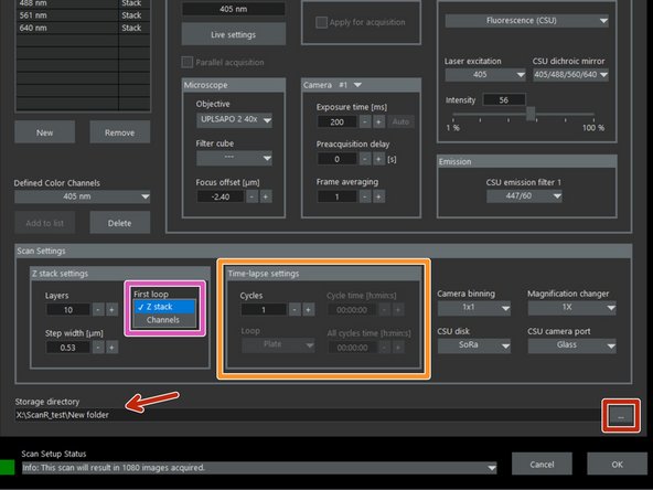
Define a "z-stack" by setting the number of planes and the spacing ("Step width").
-
If a z-stack is defined, this will be displayed in the "selected color channel" list.
-
By right clicking in the z-column of each channel one can decide if a z-stack, a single image or a z-projection should be acquired.
-
In the drop down menu "First Loop" chose the order of acquisition: Lambda before z-stack ("Z-stack"), or z before lambda ("Channels").
-
Define "Time-lapse settings" if applicable.
-
Define your destination folder for saving.
-
-
-
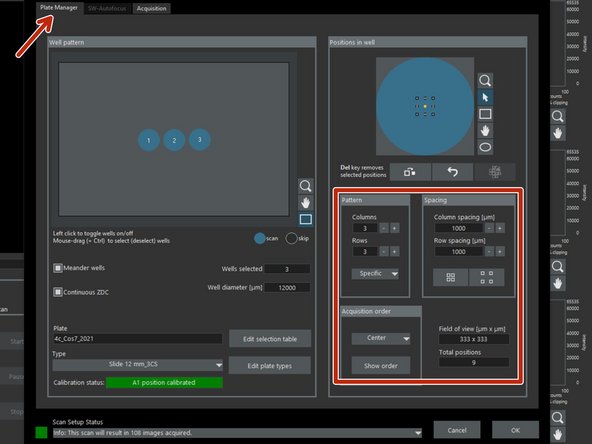
Go to "Plate Manager" tab to define your imaging pattern for each well/cover slip.
-
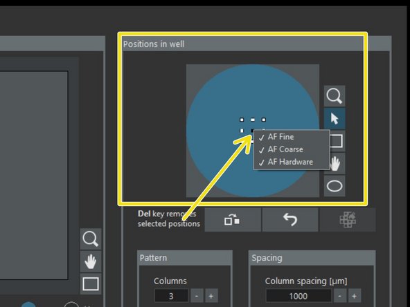
By right click in the defined positions choose the autofocus position/pattern you would like to apply in each well.
-
To optimize the acquisition we recommend that you only include one position per well with the 3 options "AF Coarse", "AF Fine" and "AF Hardware".
-
For the remaining positions "AF Fine" usually should be sufficient, but this needs to be adjusted depending on the sample. Otherwise Increase the number of positions with "AF course" and "AF Hardware".
-
-
-
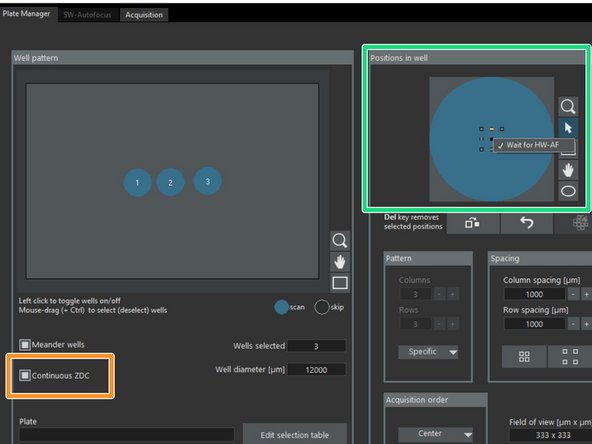
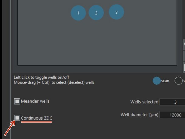
For scanning single z-plane (2D) one can activate the "Continous ZDC".
-
When doing that, the "SW-Autofocus" tab gets deactivated, as well the possibility for z-stacks.
-
The continuous hardware autofocus is meant to keep the sample automatically in focus while moving from position to position.
-
This is not applicable with the 4x Air objective.
-
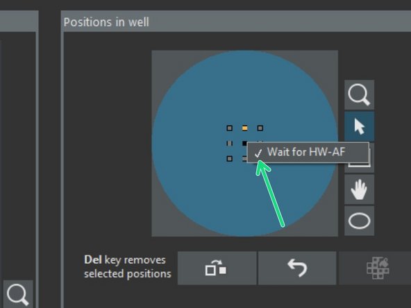
At the configuration "Positions in well" right mouse click to individual positions in order to configure for "Wait for HW-AF" (actively verifying if sample is still in focus).
-
-
-
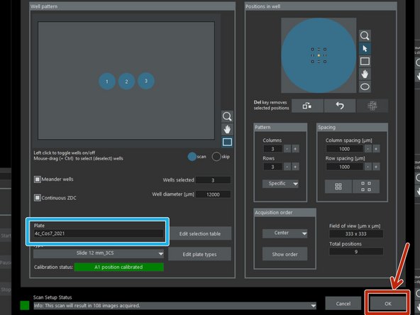
Name your plate/experiment.
-
When done with your settings click "OK".
-
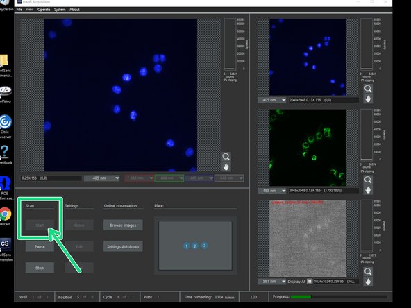
"Start" your scan.
-
-
-
Close the "ScanR Aquisition" software.
-
If immersion objectives were used clean them properly. Toggle between the objectives by using the touch screen.
-
Make sure that the 4x objective is selected and in the lowest position by following once again "Step 1" of this guide.
-
Follow the "Shut Down" procedure according to the appropriate guide.
-