Introduction
In this guide of the Center for Microscopy and Image Analysis we show how to modify scan settings at microscope located in Schlieren.
Please find detailed information about the system setup here.
-
-
"Format" defines the number of pixels in one scan area.
-
One can choose preset formats via the drop down menu.
-
By clicking the "+" every other format can be chosen.
-
Change your field of view by using the "Zoom". You can also use the knob in the external control panel.
-
Note: Format and Zoom work together in defining the pixel size in your recording. Proper setting of the xy sampling (pixel size) is crucial for acquiring optimal resolved images.
-
To adjust for the correct pixel size you can either use the online calculator such as the SVI Nyquist Calculator or the auto button for an estimate.
-
-
-
Change the scanning speed either:
-
via the drop down menu (presets)
-
via "+" for every other scan speed.
-
Increased scan speed leads to faster imaging, lower photo-damage and bleaching, but decreases signal to noise and often requires a smaller field of view.
-
Use slower scan speeds to increase the pixel dwell time and thus collect more light.
-
You can also activate "bi-directional" scanning to speed up acquisition (useful e.g. for live imaging).
-
Ensure, the phase is properly adjusted.
-
-
-
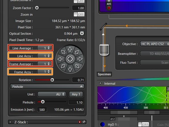
If you are limited by the laser power but still need to increase the signal (or reduce noise) use:
-
Accumulation (by line or by frame): Useful when using HyDs in counting mode or for very weak signals.
-
Averaging (by line or by frame): may be used to remove noise while using a PMT (e.g. in resonant scanning).
-
-
-
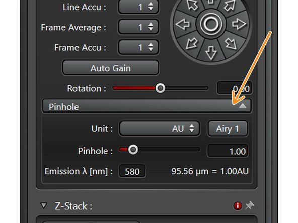
The Pinhole settings become available after clicking on the Pinhole drop down button.
-
Increasing the pinhole will enlarge the "thickness" of the z-section. In consequence you will get more light on the detector (and one can reduce laser power) while there is a loss of resolution in x, y and z dimensions.
-
We recommend not to change the pinhole size as long you are not having a good reason to do so!
-
-
-
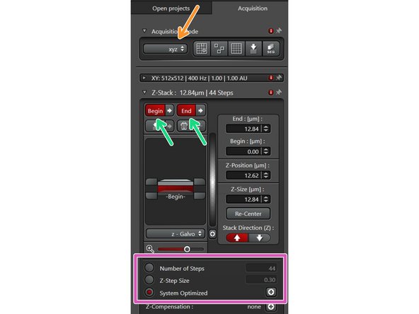
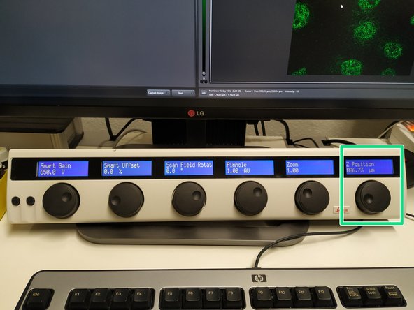
Ensure the "xyz" scan mode is selected.
-
Use the z-drive controller ("Z-Position") on the "control panel" to define the limits with "Begin" and the "End" of your z-stack.
-
Define the appropriate "Z-Step Size" or go for optimal z sampling by choosing "System Optimized". The "Number of Steps" will be automatically calculated.
-
You should refer to the SVI Nyquist Calculator if you plan to deconvolve your image as a post-processing step.
-
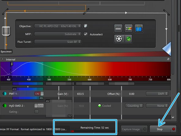
"Start" your experiment. The estimated time will be indicated here.
-