-
-
Find the allocated sample holder in the drawer that's labeled "Only Pryce Group"
-
Mount a clean standard glass slide on the holder as you normally would, keeping the metal prongs on the slide
-
Place the sample holder in the stage, enruing that the springs are correctly pressed and that the stage is as flat as possible
-
Move the stage so that roughly, the top left corner of the slide is above the objective
-
-
-
Turn on the microscope's hardware and software LasX as usual
-
Go to Configuration>>Laser configuration and turn on the Diode 405 laser.
-
For detection you will be using the PMT and not the hybrid detectors. Thus, turn on PMT 1, and make sure all HyDs are turned off.
-
Go to Acquire
-
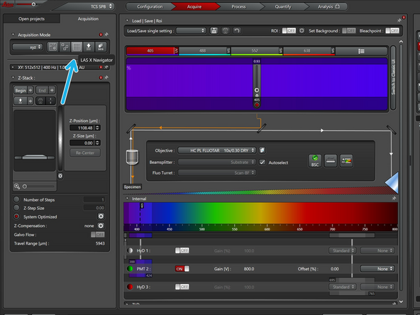
Make sure you are using the 10x objective
-
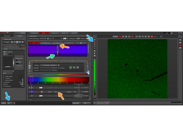
Then close the detection range of the first HyD as much as possible towards the short side of the detection range, ensuring that it is below the 405 nm wavelength
-
Place the detection range of the PMT 2 under the 405 nm range, and turn on the PMT 2
-
-
-
You will measure the maximum light reflected from the slide onto the microscopes detectors at each corner of the slide and try to adjust the height of the sample holder so that the max light reflection is detected on the same z-plane.
-
Turn on the laser to the minimum possible power lever (~0.93), and the gain high (~800). This helps to keep the direct laser light as low as possible onto the detectors, in order to not damage them.
-
Open the shutter
-
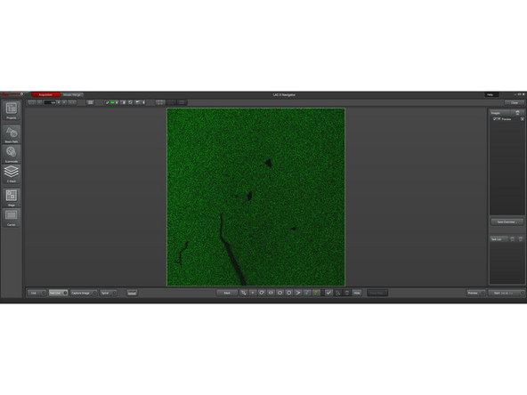
Start looking at the image "Live", making sure that the intensity is on "Auto" adjustment. At the point the objective should be as far away from the slide.
-
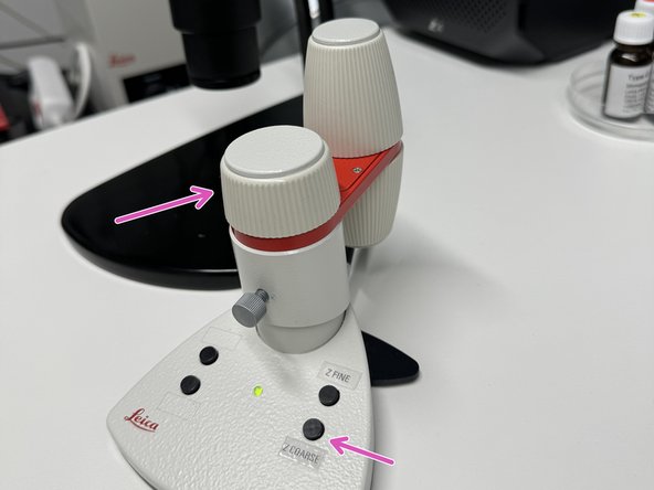
Begin moving the slide closer to the objective with the Z drive, slowly but on the coarse setting of the controller
-
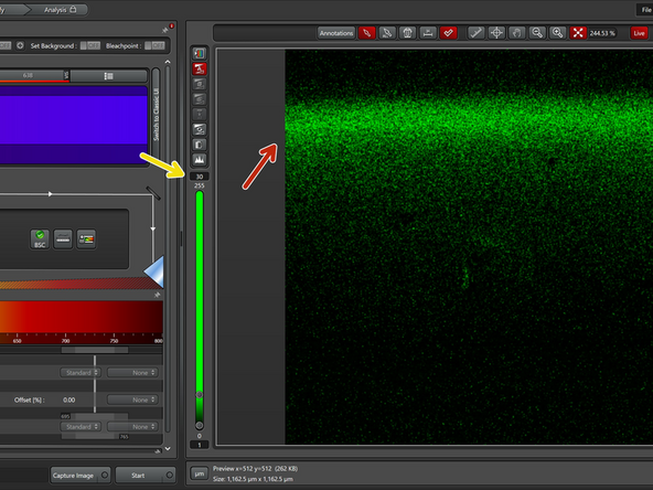
As the slide approaches the objective the laser light that is reflected on the slide will reach a maximum intensity point, when you reach this point you will see a sudden and intense increase of light on the image shown on the screen.
-
Then you will toggle up in and down in Z until you find the highest intensity point of light reflection detected on the Z axis.
-
-
-
You've found the maximum intensity of light reflection on the upper right corner of the slide (as seen on the screen). You will repeat the same process for the upper left and bottom right corners of the slide. It is not necessary to be at the exact corner, but rather roughly close to the corners of the slide; obviously, avoiding the label area
-
To be quick and precise you will use the LasX Navigator. If you've never used it, refer to this guide to familiarize yourself with it. The navigator allows you to move around the stage fast and precisely, as well as to save locations on the stage. In this case, from corner to corner of the slide
-
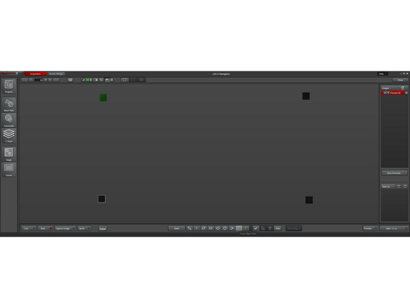
The navigator will be at the position where you have found the highest reflection Z position. To zoom out of the stage you scroll the mouse wheel towards yourself (clockwise), and if you double click a place, the stage will move to that point. With this you will define. Four imaging points close to the corners of the slide.
-
-
-
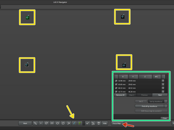
Some of the images are hard to see here on the guide, to zoom in, double click on the image and it will open on a separate window
-
Set 4 focus points approximately on the corners of the slide.
-
The x-y coordinates of the focus points you have set will appear on a list. When you double click on each location on the list, the navigator will make you to the point automatically.
-
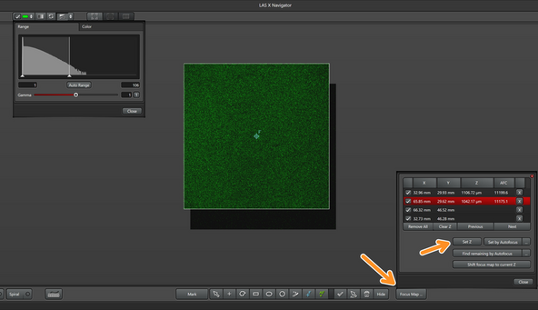
Open the locations list by clicking on Focus Map
-
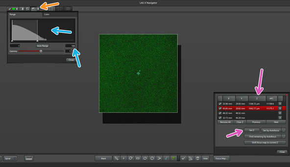
You will now measure the maximum intensity of the reflection of the slide at each of the focus point, just like you did with the first point, but here on the navigator.
-
This can be done with live imaging of each point, observing the maximum values on the histogram
-
Make sure that the auto adjustment of the histogram is on
-
Once you find the maximum reflection value at each point, you will set the Z position for each
-
-
-
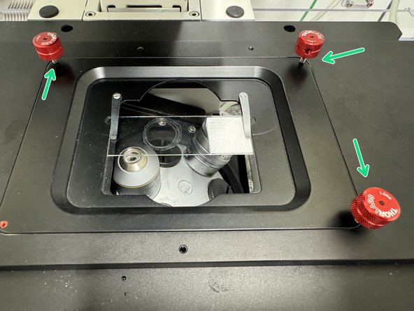
Once the z-positions of the maximum light reflection values have been found at the 4 corners have been found, you can toggle the red knobs on the sample holder in order to equalize the z-positions for all corners
-
A plane is defined by three points, thus equalizing 3 corners, should bring the last corner into plane as well
-
For the first iteration of this process you will gently turn clock wise the corners that correspond to the lowest values, and counter clockwise the corners that correspond to the highest ones.
-
Remember that you are looking at the image on the screen from below, thus make sure you are toggling with the correct corresponding knob
-
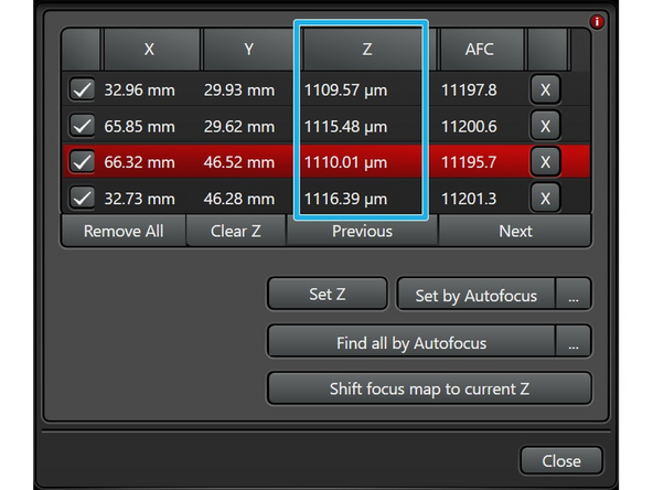
After adjusting the knobs you will repeat measuring the maximum reflection intensity values at each corner, navigating to each of them double clicking on the positions saved on the Focus map, and saving the new Z-position for each, thus updating the Focus map
-
Repeat this process until the maximum intensities' z-position at each corner is less than 10 microns range from each other.
-
-
-
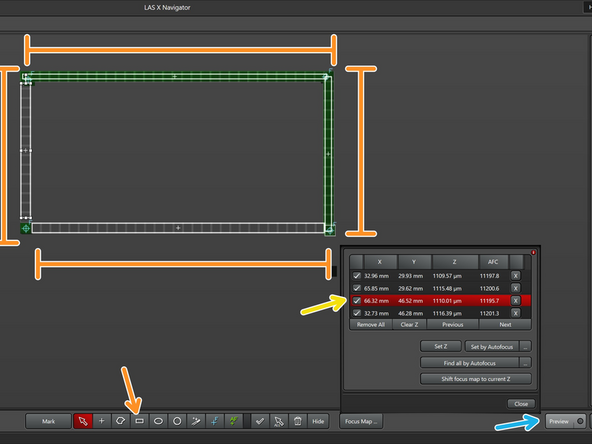
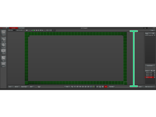
Create 4 preview regions of interest that will simulate the slide, which are one tile wide, that connect the 4 focus map locations
-
Go to one of your focus map positions
-
Start a preview
-
The resulting hollow rectangle image should look uniform in intensity across the whole imaged area, meaning that the sample is "flat", and parallel to the focal plane.
-
Is the image is not uniform, double check that your measurements and locations are correct, it is possible to forget to update them during the multiple iterations.
-