Introduction
This guide from the Center for Microscopy and Image Analysis will explain how you properly adjust the motorized correction collar of the following objectives available on ZMB instruments:
- 93x / 1.3 GLYC objective mounted at the Leica SP8 inverse STED 3X (Irchel).
- 63x / 1.2 WATER objective mounted at the Leica SP8 inverse (Gloriastrasse).
- 25x/ 1.0 WATER objective available at the Leica SP8 MP DIVE Falcon (Irchel).
Precise adjustments of the motCORR can compensate for deviations in the coverslip thickness, refractive index mismatches/specimen inhomogeneities as well as temperature changes to ensure restoration of optimal resolution, signal intensity and penetration depth.
-
-
Make sure you are in the "Acquire" tab.
-
Sample should be focused and lasers set.
-
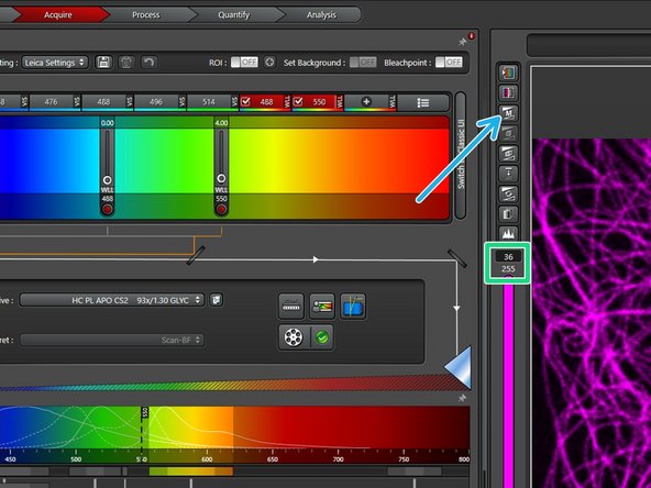
In the XY dialog open the "motCORR Collar Settings" dialog by clicking the arrow symbol.
-
Configure your setting by
-
adjusting the slider,
-
directly entering a value into the input field, or
-
alternatively via the control panel (one needs to add the desired setting).
-
Follow the next steps for correct adjustment: Steps 2 and 3 applicable for thin samples close to the coverslip, Steps 4 and 5 applicable for any kind of sample.
-
-
-
Only applicable if your sample is located close to the coverslip. If thick samples are used, the correction ring is best adjusted at the current z-level. Follow Step 4 in this case.
-
Activate a laser line (e.g. 550nm). 488 nm recommended.
-
Choose "xzy"- Scan Mode.
-
Activate a "PMT" and place the detection window underneath the chosen laser line.
-
Choose appropriate LUT. "Spectrum" recommended.
-
Open the "AOBS Configuration" window and set it to "Reflection".
-
-
-
Click "Live" to start live acquisition. Adjust "Gain [V]" and laser power appropriately without saturation.
-
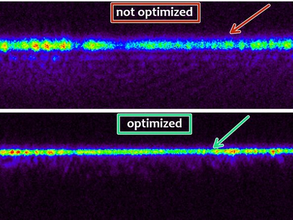
Adjust the correction ring to minimize reflection signal width corresponding to maximum intensity.
-
Not optimized.
-
Optimized.
-
If the result looks satisfying the adjustment is done.
-
-
-
Applicable for cells on cover glasses as well as thick specimen like tissue samples.
-
Best to work with the HyD detector set to counting mode.
-
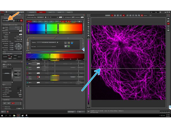
Focus your sample in the fluorescence mode. Make sure you are in the "xyz"- Scan Mode.
-
Activate "Auto-scaling" by clicking the "M" (when activated it displays an "A").
-
Carefully adjust the correction collar in one direction. The focus has to be constantly corrected.
-
Check whether the intensity and contrast of your specimen are improved - can be easily observed by the photon counts.
-
If yes, continue in the same direction and constantly check your image.
-
Finally, do this iteratively in both directions and adjust the ring to the maximum intensity and highest contrast.
-
-
-
Same procedure can also be applied to the profile view of your sample.
-
Choose "xzy" scan mode.
-
A dotted line appears in the image. Choose the area where you would like to see your cross section (xz view).
-
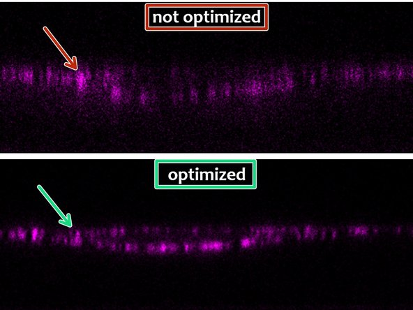
If the correction ring is set poorly your structures show low intensity, and have low resolution (large point spread function (PSF)).
-
Adjust the correction ring to minimize the PSF size corresponding to maximum intensity.
-
If the correction ring is adjusted optimally the intensity should have increased (can be observed by the photon counts) and the elongation of the PSF decreased.
-


![Click "Live" to start live acquisition. Adjust "Gain [V]" and laser power appropriately without saturation.](https://d3t0tbmlie281e.cloudfront.net/igi/zmb/NZb2CQylYawXZmnM.medium)