Introduction
In this guide of the Center for Microscopy and Image Analysis you will learn how to generate or modify well plate definitions for optimally imaging your specific well plates, slides or sample carriers.
This guide does not explain basic microscope operation. Please check out the other InCell guides for that.
-
-
Load your plate.
-
Go to "Aplication/ Plate/Slide Manager".
-
Select a plate definition which is similar to your plate.
-
This guide shows how to generate a new plate definition. The workflow for generating a slide definition is identical. "Plate" and "Slide" is used interchangeable in this guide.
-
The difference between a plate and a slide definition is the automatically used hardware auto-focus strategy. For slide definitions the air/glas interface is localized and a fix offset (glas thickness + measured offset) is taken. For plate definitions the air-glas and glas-water interfaces are localized and a measured offset is taken from there.
-
-
-
Copy the chosen plate definition.
-
Save it with a new name.
-
Alternatively a plate definition can also be generated from scratch.
-
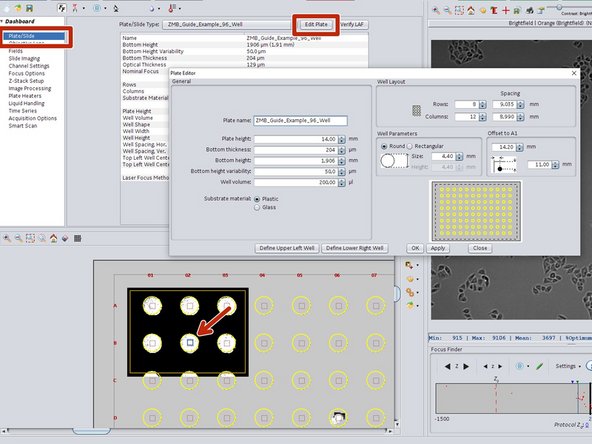
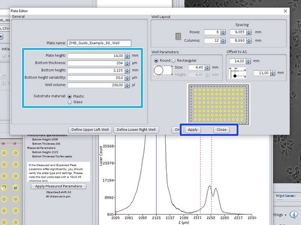
In the automatically opened "Plate Editor" enter all the known values of your plate.
-
Click "Apply" and "Close" to save the settings.
-
-
-
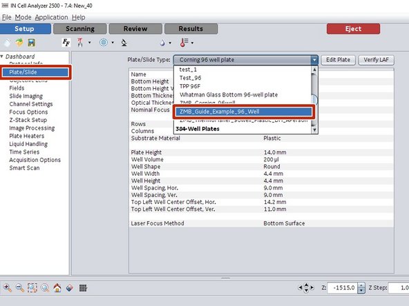
In "Dashboard/ Plate/Slide" select your newly generated plate definition.
-
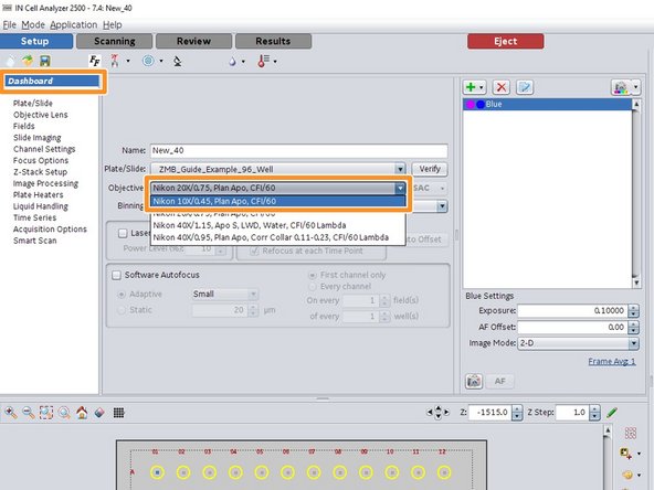
Select the 10x objective.
-
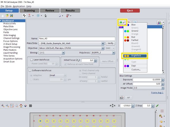
Add a "Brightfield" channel.
-
-
-
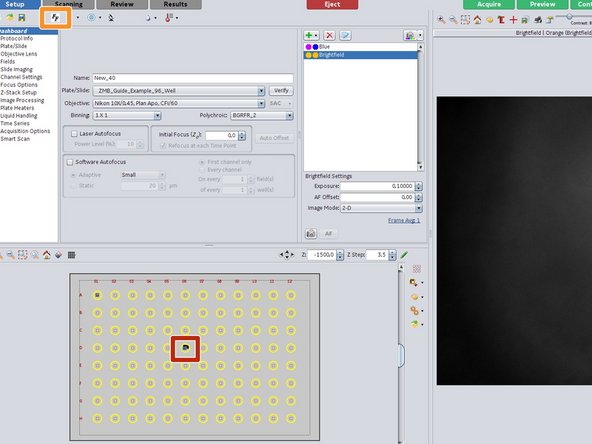
Click into the center of a well for moving the stage and for positioning the well plate.
-
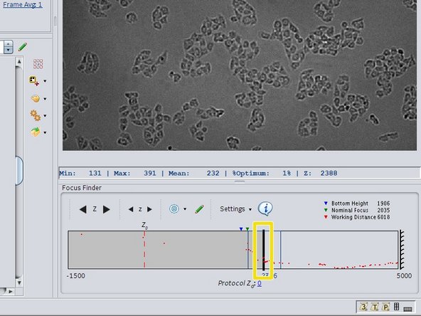
Open the focus finder tool.
-
Use the focus slider to roughly focus on on your sample.
-
-
-
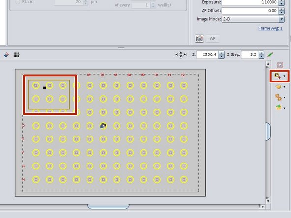
Use the preview tool to draw a preview area in your plate.
-
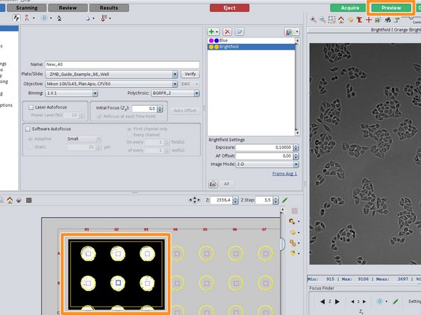
Click on "Preview" to generate the preview of the selected area.
-
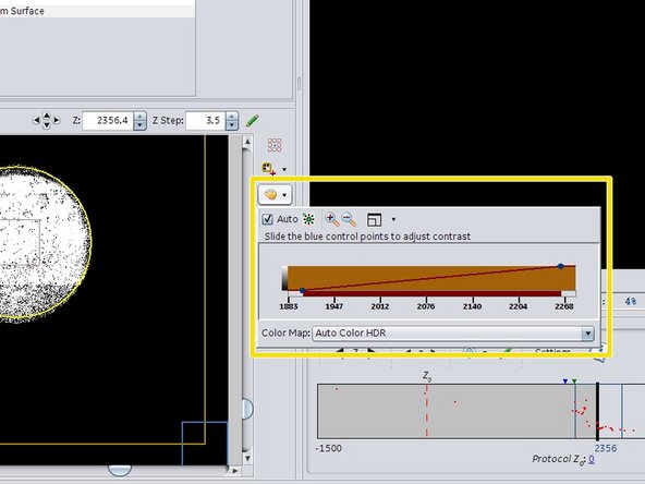
Adjust the visualization contrast of the preview when needed.
-
-
-
Go to "Dashboard/ Plate/Slide" and "Edit Plate" to adjust the plate settings. The yellow well indicator should fit your well.
-
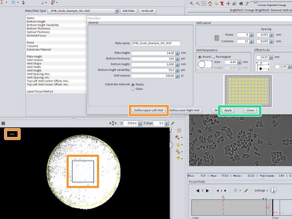
The easiest way to adjust the plate geometry is by zooming in (mouse wheel) and clicking into the very center of well A1 and then on "Define Upper Left Well".
-
Click "Apply" followed by "Yes" to save the new values in your plate definition and close the "Plate Editor".
-
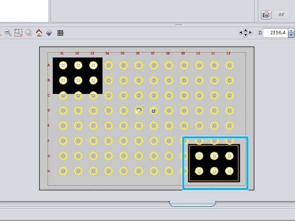
Repeat the preview and the adjustment step in the lower right corner of your well plate and "Define Lower Right Well".
-
-
-
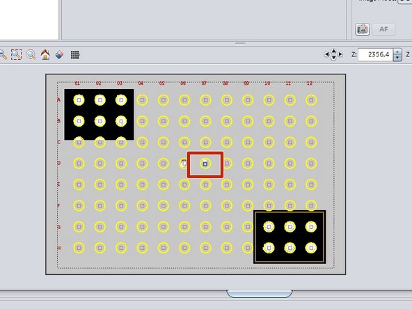
To move the stage, click into the center of a well in the middle of your plate.
-
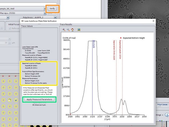
In the "Dashboard" click on "Verify" to invoke the hardware auto-focus.
-
Compare the "Plate Parameters" with the "Measured parameters". If they are off click on "Apply Measured Parameters".
-
Check the new values as measured by the hardware auto focus.
-
Click "Apply" followed by "Yes" to save the new values in your plate definition and close the "Plate Editor".
-
Your new plate definition is now ready for being used in your experiment.
-
-
-
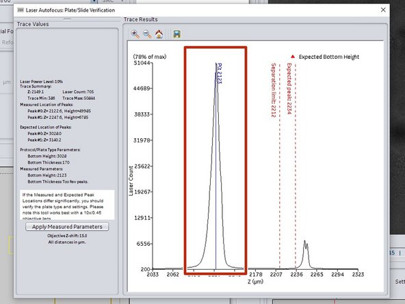
When using a slide instead of a plate definition, the hardware auto-focus only searches for the first reflection peak (air-glas interface).
-
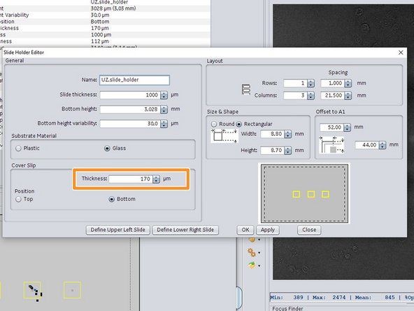
Using high quality cover slips (170 micrometers) together with setting the proper "Thickness" value in the "Plate Editor" is crucial for optimal auto-focus performance.
-
When auto focusing using a slide definition fails, you can try to generate and use a plate definition instead. Usually the second reflection peak in slides is still high enough for being localized and used by the auto-focus.
-